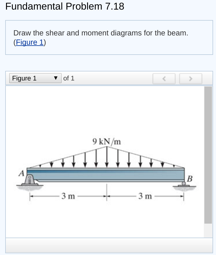
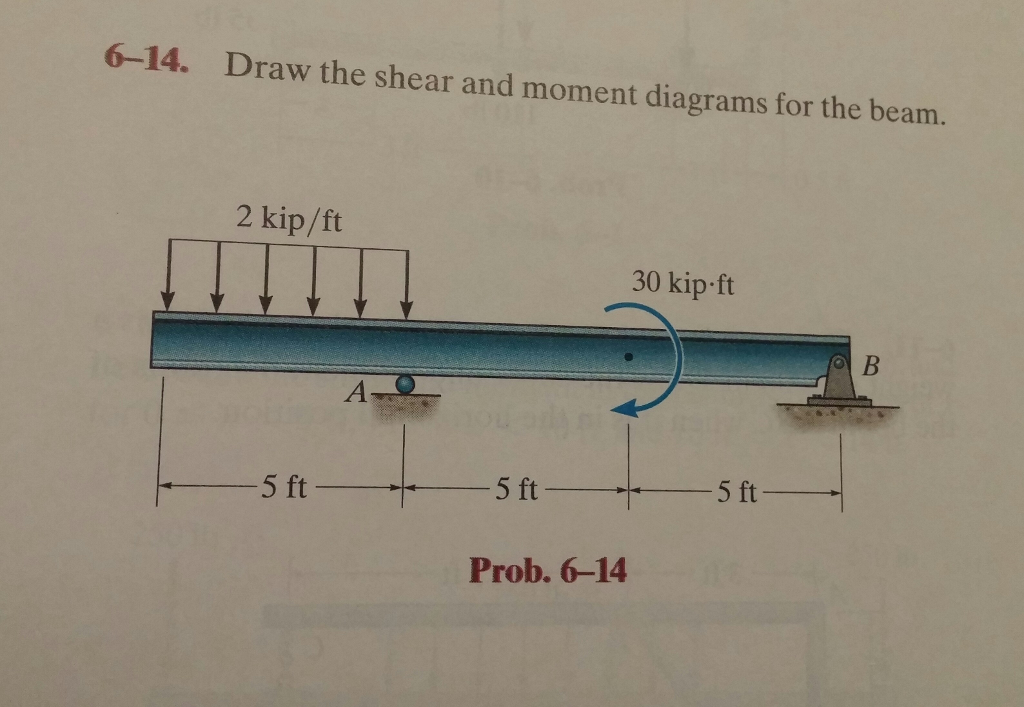
6-14 Draw The Shear And Moment Diagrams For The Beam
6-14 Draw The Shear And Moment Diagrams For The Beam - Here, ${a_x}$ is the horizontal component of support a, ${a_y}$ is the vertical component of support a and ${n_c}$ is the normal force reaction at support c. Web shear force and bending moment diagrams are powerful graphical methods that are used to analyze a beam under loading. Web shear/moment diagrams are graphical representations of the internal shear force and bending moment along the whole beam. This page will walk you through what shear forces and bending moments are, why they are useful, the procedure for drawing the diagrams and some other keys aspects as well. Draw the shear and moment diagrams for the beam, and determine the shear and moment throughout the beam as functions of x. For o s x 6 n: Web shear & bending moment diagrams. Statics, 14th edition russell c. Please let me know if. They can be constructed by establishing a sign convention. You'll get a detailed solution from a subject matter expert that helps you learn core concepts. A) determine the reactions at the supports. The reactions shown on the diagram are determined from equilibrium equations as. Web shear/moment diagrams are graphical representations of the internal shear force and bending moment along the whole beam. This page will walk you through what. Web this problem has been solved! Draw the shear force and bending moment diagrams for the beam show below: Draw the shear and moment diagrams for the beam, and determine the shear and moment in the beam as functions of x for 0 x 4 ft, 4 ft x 10 ft, and 10 ft x 14 ft 250 lb 250. Web this problem has been solved! Shear and moment diagrams and formulas are excerpted from the western woods use book, 4th edition, and are provided herein as a courtesy of western wood products association. Draw the shear and moment diagrams for the beam, and determine the shear and moment throughout the beam as functions of x for 0≤x≤6ft and 6ft≤x≤10ft.. Draw the shear and moment diagrams for the overhang beam. Shear and moment diagrams are graphical representations of the variation of shear force and bending moment along the length of a structural element such as a beam. Please let me know if. In each problem, let x be the distance measured from left end of the beam. Neglect the mass. Draw the shear and moment diagrams for the beam, and determine the shear and moment throughout the beam as functions of x. We go through breaking a beam into segments, and then we learn about the relationships between shear force and moment. Draw the shear and moment diagrams for the beam, and determine the shear and moment in the beam. In general the process goes like this:1) calcul. They can be constructed by establishing a sign convention. Web we are asked to draw the shear and moment diagrams for the beam. This page will walk you through what shear forces and bending moments are, why they are useful, the procedure for drawing the diagrams and some other keys aspects as. We go through breaking a beam into segments, and then we learn about the relationships between shear force and moment. Draw the shear force and bending moment diagrams for the beam show below: Web shear/moment diagrams are graphical representations of the internal shear force and bending moment along the whole beam. Web this problem has been solved! They can be. Web shear force and bending moment diagrams are analytical tools used in conjunction with structural analysis to help perform structural design by determining the value of shear forces and bending moments at a given point of a structural element such as a beam. Please let me know if. Shear and moment diagrams and formulas are excerpted from the western woods. Shear and moment diagrams are graphical representations of the variation of shear force and bending moment along the length of a structural element such as a beam. Web this problem has been solved! Draw the shear and moment diagrams for the beam, and determine the shear and moment throughout the beam 10 kip 2 kip/ft g kip 8 kip 40. Please let me know if. Write shear and moment equations for the beams in the following problems. Draw the shear and moment diagrams for the beam, and determine the shear and moment throughout the beam as functions of x for 0≤x≤6ft and 6ft≤x≤10ft. Web to design a beam, it is essential to determine the maximum shear and moment in the. Also, draw shear and moment diagrams, specifying values at all change of loading positions and at points of zero shear. Shear and moment diagrams and formulas are excerpted from the western woods use book, 4th edition, and are provided herein as a courtesy of western wood products association. Web this is an example problem that will show you how to graphically draw a shear and moment diagram for a beam. Hibbeler thank you guys for watching. Draw the shear and moment diagrams for the beam, and determine the shear and moment throughout the beam as functions of x for 0≤x≤6ft and 6ft≤x≤10ft. Web figures 1 through 32 provide a series of shear and moment diagrams with accompanying formulas for design of beams under various static loading conditions. This page will walk you through what shear forces and bending moments are, why they are useful, the procedure for drawing the diagrams and some other keys aspects as well. Web shear/moment diagrams are graphical representations of the internal shear force and bending moment along the whole beam. Web this problem has been solved! If the cross section of the beam is rectangular with height of 0.2ft and width of 0.1ft, and the beam has a young's modulus of 29e3ksi, please identify which location. Web the determination of the internal force system acting at a given section of a beam : Draw the shear and moment diagrams for the beam, and determine the shear and moment throughout the beam 10 kip 2 kip/ft g kip 8 kip 40 kip.ft as functions of x. 2 kip/ft 30 kip ft 5 ft 5 ft 5 ft prob. You'll get a detailed solution from a subject matter expert that helps you learn core concepts. In the fbd, the directions of the unknown force and moment are assumed positive according to the member sign convention. Web this problem has been solved!
Solved Draw the shear and moment diagrams for the beam.
Solved Draw the shear and moment diagrams for the beam.

Solved Draw the shear and moment diagrams for the beam (a)

Solved Draw the shear and moment diagrams for the beam, and

Drawing Shear and Moment Diagrams for Beam YouTube
Solved Draw the shear and moment diagrams for the beam
Solved 614. Draw the shear and moment diagrams for the

Shear force and bending moment diagrams for beams pdf

Learn How To Draw Shear Force And Bending Moment Diagrams Engineering

Learn How To Draw Shear Force And Bending Moment Diagrams Engineering
Web Learn To Draw Shear Force And Moment Diagrams Using 2 Methods, Step By Step.
Statics, 14Th Edition Russell C.
Representations Of The Internal Shears And Moments Within A Beam.
For O S X 6 N:
Related Post: