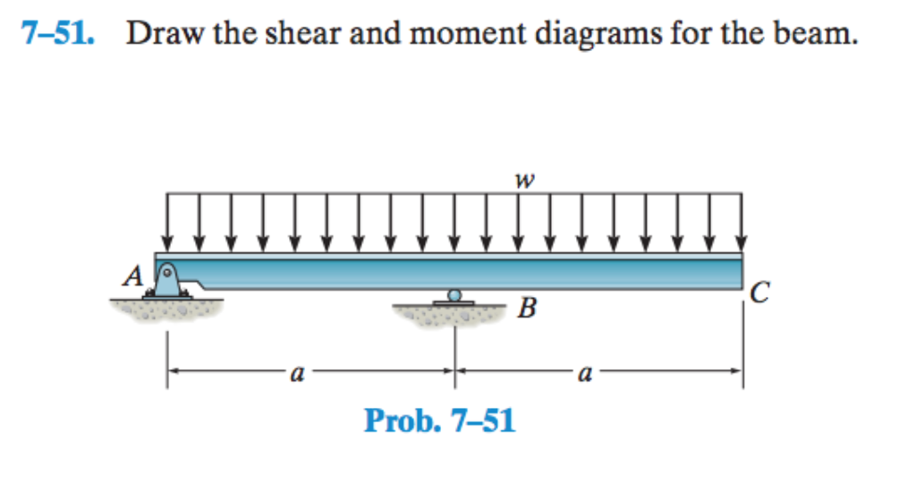
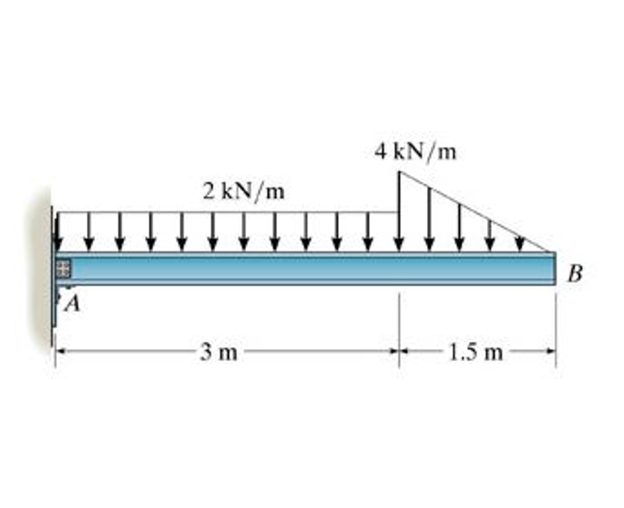
7-51 Draw The Shear And Moment Diagrams For The Beam
7-51 Draw The Shear And Moment Diagrams For The Beam - By drawing the free body diagram you identify all of these loads and show then on a sketch. Web learn to draw shear force and moment diagrams using 2 methods, step by step. One of the ways to do this is through the use of shear and moment diagrams. Skyciv beam tool guides users along a professional beam calculation workflow, culminating in the ability to view and determine if they comply with your region's design codes. Web r = span length of the bending member, in. View the full answer step 2 step 3 final answer previous question next question transcribed image text: Shear and moment diagrams are graphical representations of the variation of shear force and bending moment along the length of a structural element such as a beam. Also, draw shear and moment diagrams, specifying values at all change of loading positions and at. Web this problem has been solved! T 777 draw the shear and moment diagrams for the beam. W = load per unit length, lbs./in. 3kn/m 10kn 6m b resultant moment about point a: Draw the shear and moment diagrams for the beam. You'll get a detailed solution from a subject matter expert that helps you learn core concepts. Web the first step in calculating these quantities and their spatial variation consists of constructing shear and bending moment. Draw a free body diagram showing and labeling all load forces and support (reaction) forces, as well as any. Draw the shear and moment diagrams for the beam.problem from engineering mechanics statics, fifteenth edition. Web the two expressions above give the value of the internal shear force and bending moment in the beam, between the distances of the 10 ft.. Draw the shear and moment diagrams for the beam. Web to design a beam, it is essential to determine the maximum shear and moment in the structure. You'll get a detailed solution from a subject matter expert that helps you learn core concepts. Establish the m and x axes and plot the values of the moment at the ends of. 3kn/m 10kn 6m b resultant moment about point a: Draw a free body diagram showing and labeling all load forces and support (reaction) forces, as well as any. Web draw the shear force and bending moment diagrams for the beam shown in the figure, when dimensions and loadings of the beam get values a=1.0 m,b=1 m,c=3.2 m,d=0.8 m,f=16 kn,p=12 kn. This problem has been solved! The following sections will describe how these diagrams are made. 3kn/m 10kn 6m b resultant moment about point a: Also, draw shear and moment diagrams, specifying values at all change of loading positions and at. By drawing the free body diagram you identify all of these loads and show then on a sketch. Web r = span length of the bending member, in. Draw the shear and moment diagrams for the beam. Web this problem has been solved! In general the process goes like this:1) calcul. Skyciv beam tool guides users along a professional beam calculation workflow, culminating in the ability to view and determine if they comply with your region's design codes. Calculate the reactions using the equilibrium equations (may not need to do this if choosing a cantilever beam and using the free side for the fbd). Web the two expressions above give the value of the internal shear force and bending moment in the beam, between the distances of the 10 ft. Web 7.51 draw the shear and moment diagrams. Draw the shear and moment diagrams for the beam. Calculate the reactions using the equilibrium equations (may not need to do this if choosing a cantilever beam and using the free side for the fbd). Web the two expressions above give the value of the internal shear force and bending moment in the beam, between the distances of the 10. Give support reactions positive values. By drawing the free body diagram you identify all of these loads and show then on a sketch. Shear force and bending moment diagrams for our loaded beam. Web step 1 | draw a free body diagram. Draw the shear and moment diagrams for the beam. Establish the m and x axes and plot the values of the moment at the ends of the beam. This problem has been solved! In the questions the location x proceeds from left to right! Web 7.51 draw the shear and moment diagrams for the beam? Draw the shear and moment diagrams for the beam. Draw the shear and moment diagrams for the beam. Draw the shear and moment diagrams for the beam. Web draw the shear force and bending moment diagrams for the beam shown in the figure, when dimensions and loadings of the beam get values a=1.0 m,b=1 m,c=3.2 m,d=0.8 m,f=16 kn,p=12 kn and q=23kn//m. Moment = 0 therefore, the final answer in bold latex. Calculate the reactions using the equilibrium equations (may not need to do this if choosing a cantilever beam and using the free side for the fbd). Draw the shear and moment diagrams for the beam.problem from engineering mechanics statics, fifteenth edition. 1.2 ft ' 1.2 ft fig. Skyciv beam tool guides users along a professional beam calculation workflow, culminating in the ability to view and determine if they comply with your region's design codes. Web this problem has been solved! P7.51 this problem has been solved! Web our calculator generates the reactions, shear force diagrams (sfd), bending moment diagrams (bmd), deflection, and stress of a cantilever beam or simply supported beam. R = reaction load at bearing point, lbs. W a с b 를 l prob. Web the two expressions above give the value of the internal shear force and bending moment in the beam, between the distances of the 10 ft. You'll get a detailed solution from a subject matter expert that helps you learn core concepts. You'll get a detailed solution from a subject matter expert that helps you learn core concepts.
Solved Draw the shear and moment diagrams for the beam.
Solved 751. Draw the shear and moment diagrams for the

Solved Draw the shear and moment diagrams for the beam, and
Solved Draw the shear diagram for the beam. Follow

Learn How To Draw Shear Force And Bending Moment Diagrams Engineering

Drawing Shear and Moment Diagrams for Beam YouTube

Shear And Moment Diagrams For Beams

Learn How To Draw Shear Force And Bending Moment Diagrams Engineering

Learn How To Draw Shear Force And Bending Moment Diagrams Engineering

Draw the shear and moment diagrams for the beam.
Web The First Step In Calculating These Quantities And Their Spatial Variation Consists Of Constructing Shear And Bending Moment Diagrams, \(V(X)\) And \(M(X)\), Which Are The Internal Shearing Forces And Bending Moments Induced In The Beam, Plotted Along The Beam's Length.
Also, Draw Shear And Moment Diagrams, Specifying Values At All Change Of Loading Positions And At.
You'll Get A Detailed Solution From A Subject Matter Expert That Helps You Learn Core Concepts.
One Of The Ways To Do This Is Through The Use Of Shear And Moment Diagrams.
Related Post: