Draw Isometric Piping Drawings
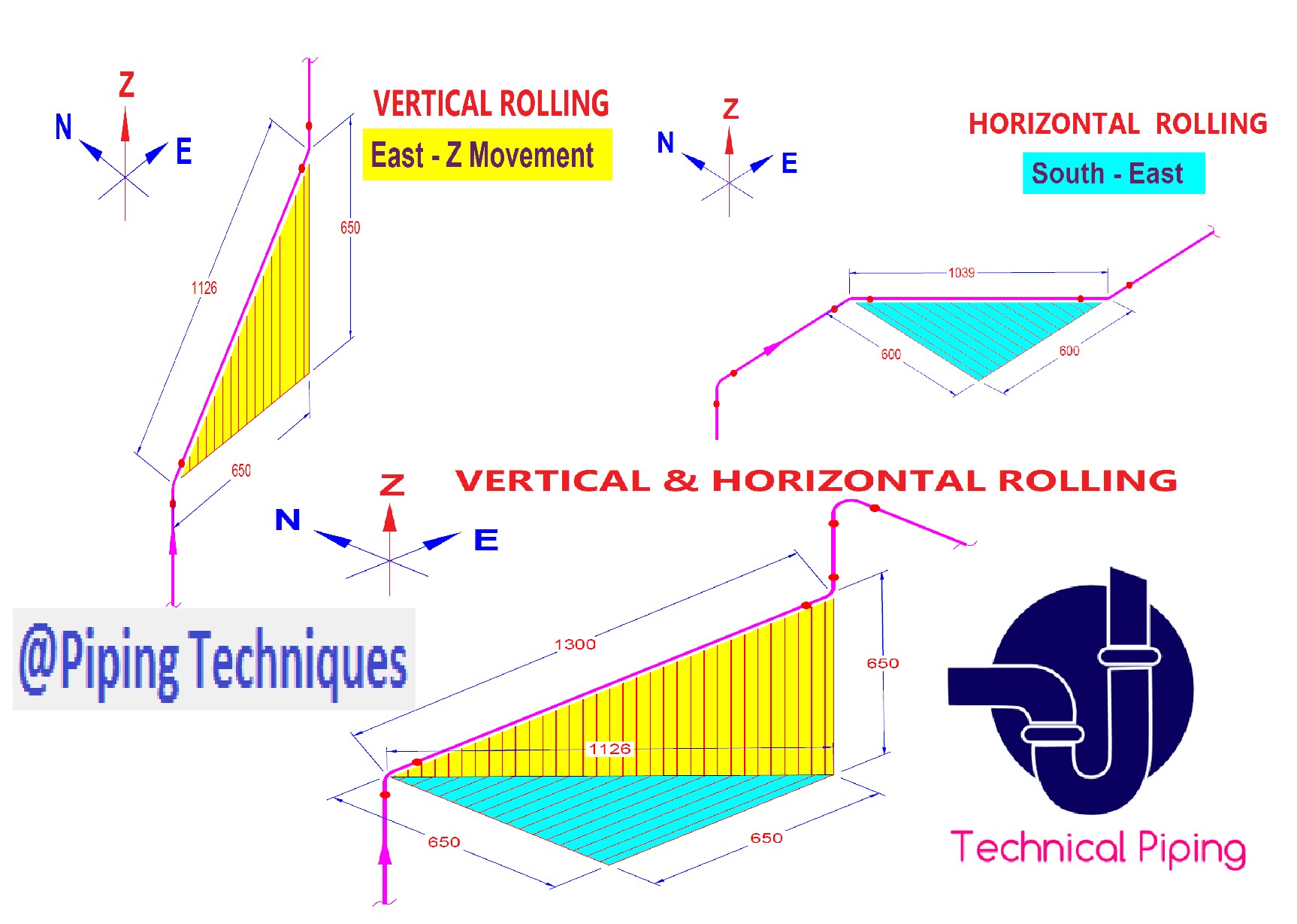
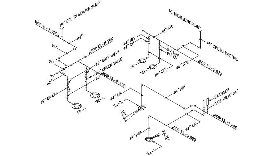
Draw Isometric Piping Drawings - Isometrics are not drawn to scale but should be proportional to easy understanding. Isometric drawings are particularly important during the construction phase of a project. Web an isometric drawing covers a complete line as per the line list and p&id. Web an isometric drawing is a type of pictorial drawing in which three sides of an object can be seen in one view. It shows all information necessary for fabrication and erection. 3 clicks to draw a pipe, 3 clicks to add an elbow, 1 click to add a dimension and 3 clicks to print. Web the isometrics drawing are created from information found on a plan and elevation views. Create a drawing sheet for isometrics. Usually, piping isometrics are drawn on preprinted paper, with lines of equilateral triangles form of 60°. Trace the flow of a process stream into your piping isometrics, through the pipes and equipment, and out of the piping isometrics. Web an isometric drawing covers a complete line as per the line list and p&id. What is piping isometric drawing? In isometric drawings, pipes are represented as lines. Web how to draw isometric drawings. Usually, piping isometrics are drawn on preprinted paper, with lines of equilateral triangles form of 60°. In isometric drawings, pipes are represented as lines. Create a drawing sheet for isometrics. The principal dimensions are the limits of size for the object along the three principal directions. How to read iso drawings. Automated bill of materials no more tedious material tracking when creating a pipe isometric drawing. Easy isometric interface import idf or pcf files allows for flexible drawing track spools spoolfab's inventory system enables the automatic inventorying and subsequent generation of reports such as: Web isometric drawings are typically used to show the details of a piping system, such as the size and type of piping, the direction of flow of the fluids, and the location. When using software, it is. Symbols are shown in black lines. The process of drafting isometric drawings for a pipeline system involves referencing the arrangements of the pipelines, sections, and elevation drawings during its development. Usually, piping isometrics are drawn on preprinted paper, with lines of equilateral triangles form of 60°. It shows all information necessary for fabrication and erection. The principal dimensions are the limits of size for the object along the three principal directions. Web piping isometric drawing types of piping drawings for designing processes or power piping, mostly five types of piping drawings are developed. Accurate drawing symbols, callouts, precise coordinates, and elevations provide intricate information to the fabricator. When using software, it is. Isometric drawings are. Symbols like fittings, valves and flanges are modified to adapt to the isometric grid. 3 clicks to draw a pipe, 3 clicks to add an elbow, 1 click to add a dimension and 3 clicks to print. It shows all information necessary for fabrication and erection. Second, draw the pipeline with the help of simple lines. Test your knowledge with. Symbols are shown in black lines. Web we are concluding our first pipefitter series run with a video on how to draw isometric drawings. Web how to read piping isometric drawing symbols. Section of left or right of piping isometric drawing includes: These drawings are developed from the schematics, basic design basis, and specifications for process piping. Web we are concluding our first pipefitter series run with a video on how to draw isometric drawings. Second, draw the pipeline with the help of simple lines. It shows all information necessary for fabrication and erection. First create a drawing sheet in din a4 or a3 and activate the isometric grid. Trace the flow of a process stream into. The process of drafting isometric drawings for a pipeline system involves referencing the arrangements of the pipelines, sections, and elevation drawings during its development. Web an isometric drawing covers a complete line as per the line list and p&id. First create a drawing sheet in din a4 or a3 and activate the isometric grid. Reading a piping isometric drawing basic. Dimension is given relative to. Second, draw the pipeline with the help of simple lines. Piping fabrication work is based on isometric drawings. Web create isometric drawings in minutes: Symbols like fittings, valves and flanges are modified to adapt to the isometric grid. Trace the flow of a process stream into your piping isometrics, through the pipes and equipment, and out of the piping isometrics. Symbols like fittings, valves and flanges are modified to adapt to the isometric grid. Dimension is given relative to. Web know the lettering and numbering standards for piping, instruments and equipment designation on your piping isometrics. Isometrics are not drawn to scale but should be proportional to easy understanding. These drawings are developed from the schematics, basic design basis, and specifications for process piping. Reading a piping isometric drawing basic training. Among various applications, isometric drawing finds extensive use in the field of engineering, particularly in the design and construction of pipes. In isometric drawings, pipes are represented as lines. Web piping isometric drawing is a 2d drawing that represents the 3d piping system in pictorial form for helping in fabrication and construction. Isometric drawings are particularly important during the construction phase of a project. Web tutorial piping tips and tricks. Web the isometrics drawing are created from information found on a plan and elevation views. Lighter lines show connected pipe, and are not parts of the symbols. Web isometric drawings are typically used to show the details of a piping system, such as the size and type of piping, the direction of flow of the fluids, and the location of valves, pumps, and other equipment nozzles. Web the main body of a piping isometric drawing is consist of:
How to read piping isometric drawing, Pipe fitter training, Watch the

How to read isometric drawing piping dadver

Piping isometric drawing examples mazorama

Piping Isometric Drawing Exercises Pdf at GetDrawings Free download

Piping Design Basics Piping Isometric Drawings Piping Isometrics

Piping isometric drawing examples planninglio

Revit AddOns EzISO Piping Models to Isometric Drawings

Learn isometric drawings (piping isometric)
Piping Isometric Drawings Autodesk Community

Isometric Piping Drawings Advenser
When Using Software, It Is.
Web Create Isometric Drawings In Minutes:
Weld Joint Type And Its Location;
These Various Types Of Piping Drawings In Engineering Organizations Are:
Related Post:
