Drawing Piping Isometrics
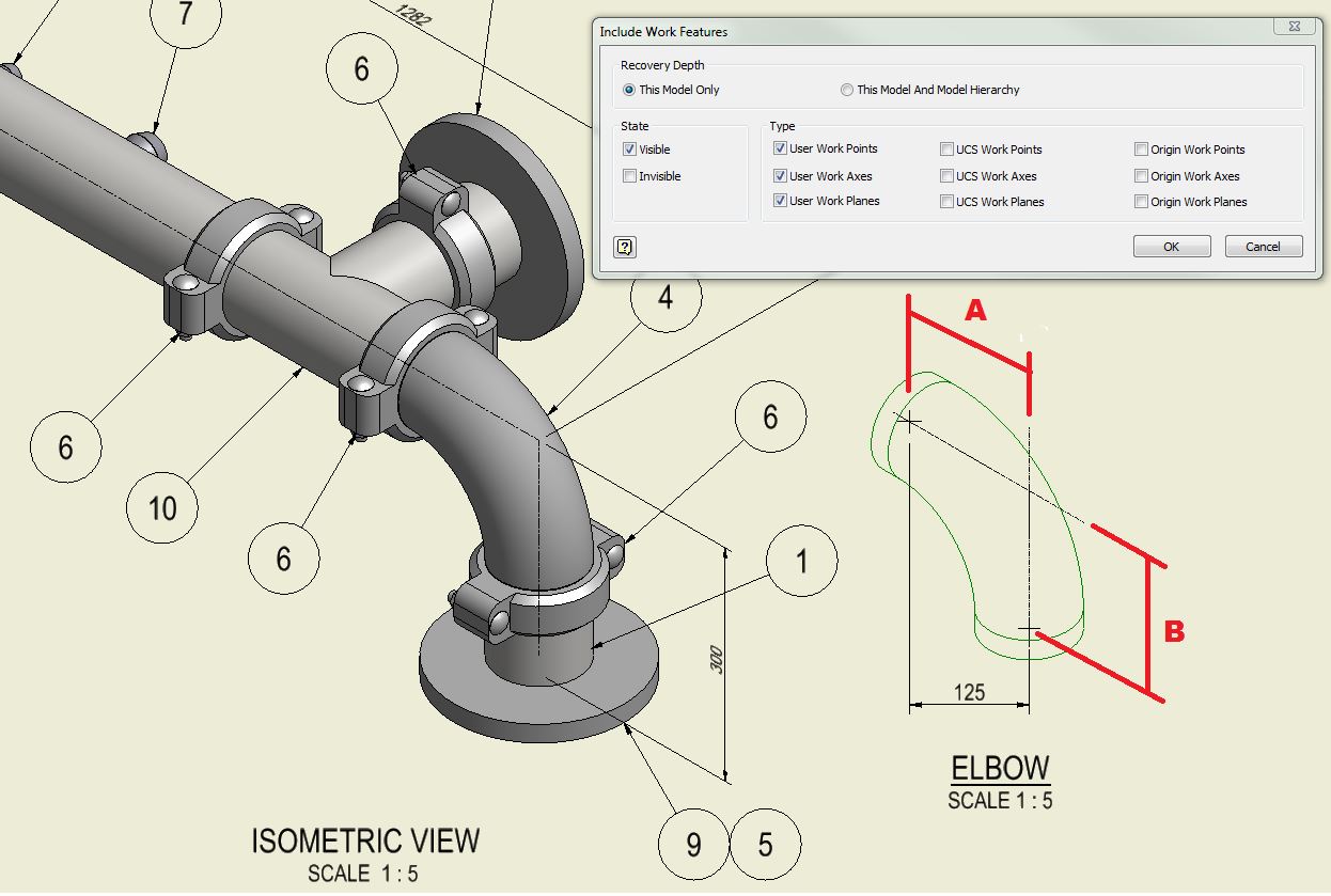
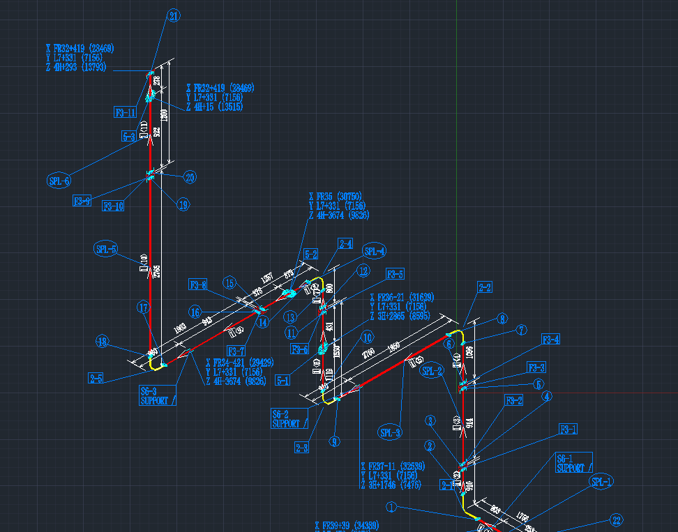
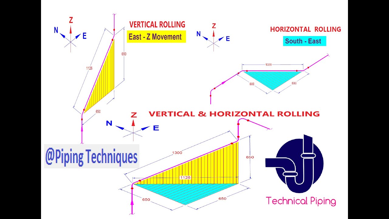
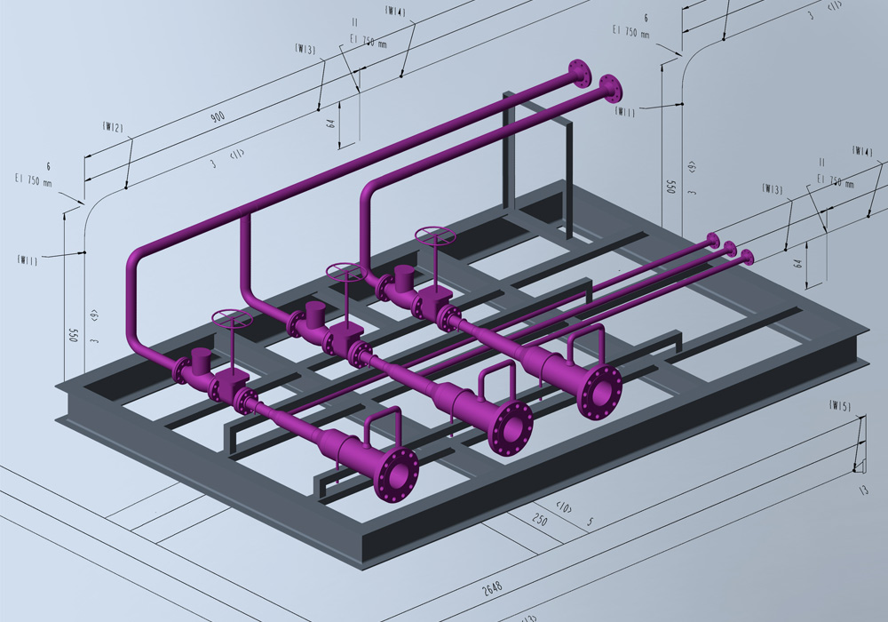
Drawing Piping Isometrics - Piping isometric drawing consists of three sections. Isometric drawings are typically used to show the details of a piping system, such as the size and type of piping, the direction of flow of the fluids, and the location of valves, pumps, and other equipment nozzles. Automated bill of materials no more tedious material tracking when creating a pipe isometric drawing. These drawings have become an indispensable tool for representing complex pipeline structures. Sizing table 710.1(1) testing 312; Web abstract an extensive discussion of the need for, and development of, piping isometric drawings is provided. Page 1 of 1 this publication can be made availabl e in alternate formats (braille, large print or d igital media) upon request. Dimension is given relative to. Web piping fabrication work is based on isometric drawings. Connection to building drain 708.1.3; By definition, isometrics drawings are a graphic representation of a 3d routed line in a 2d plane that combines height, length of pipe in a single drawing with a 30º angle on both sides from horizontal. Web tutorial piping tips and tricks. Has anyone created an isometric gas plan layout in chief. They are used for the documentation and production. Separation from water service 603.2; They are used for the documentation and production of complex pipework. Web creating piping isometric drawings involves the use of various tools and software, both traditional and digital. Web piping isometrics drawing are a type of pictorial drawings that show the three principal dimensions of an object in one view. I am getting more and. Web 0:00 / 5:44 how to read piping isometric drawing symbols. Piping isometric drawing consists of three sections. This section explores the available options and their characteristics: These drawings have become an indispensable tool for representing complex pipeline structures. It’s popular within the process piping industry because it can be laid out and drawn with ease and portrays the object. They are used for the documentation and production of complex pipework. Separation from water service 603.2; This section explores the available options and their characteristics: Unlike orthographics, piping isometrics allow the pipe to be drawn in a manner by which the length, width and depth are shown in a single view. Symbols like fittings, valves and flanges are modified to. I think it is just silly that i have to do one in the first place because i would just be guessin. Web piping isometrics drawing are a type of pictorial drawings that show the three principal dimensions of an object in one view. Isometric drawings are typically used to show the details of a piping system, such as the. Trace the flow of a process stream into your piping isometrics, through the pipes and equipment, and out of the piping isometrics. In same trench as storm sewer 703.3; Has anyone created an isometric gas plan layout in chief. Web an isometric drawing covers a complete line as per the line list and p&id. I am getting more and more. An explanation of how piping isometrics are created from plan and elevation views is explained. Piping symbols and various pipeline drawings are intricately linked to isometrics, highlighting their importance in the. Web 0:00 / 5:44 how to read piping isometric drawing symbols. Reading a piping isometric drawing basic training. Gas pipe sizing calculations and isometric ifgc 402.3. Web we are concluding our first pipefitter series run with a video on how to draw isometric drawings. Symbols like fittings, valves and flanges are modified to adapt to the isometric grid. Web an isometric drawing covers a complete line as per the line list and p&id. Has anyone created an isometric gas plan layout in chief. The symbols that. It shows all information necessary for fabrication and erection. Web abstract an extensive discussion of the need for, and development of, piping isometric drawings is provided. Web the isometrics drawing are created from information found on a plan and elevation views. Dimension is given relative to. Isometrics are not drawn to scale but should be proportional to easy understanding. Web in same trench as nonpotable water piping 1301.11; Web creating piping isometric drawings involves the use of various tools and software, both traditional and digital. It shows all information necessary for fabrication and erection. And affi x this letter within the drawing pack age, ibc 107.2. Web we are concluding our first pipefitter series run with a video on. Page 1 of 1 this publication can be made availabl e in alternate formats (braille, large print or d igital media) upon request. The clear advantage of a piping isometric drawing is its simplicity and symbolic representation of pipework, which allows it to be read quickly by all project stakeholders. Piping isometric drawing consists of three sections. This section explores the available options and their characteristics: Main graphic section consist of isometric representation of a pipe line route in 3d space, which includes following information : Dimension is given relative to. I am getting more and more comments from the cities to provide an isometric gas line plan and have not come up with a good way to create one. Web abstract an extensive discussion of the need for, and development of, piping isometric drawings is provided. Test your knowledge with our 50+ quiz questions. The principal dimensions are the limits of size for the object along the three principal directions. Separation from water service 603.2; Unlike orthographics, piping isometrics allow the pipe to be drawn in a manner by which the length, width and depth are shown in a single view. The use of a north arrow in establishing pipe orientation and routing on the isometric is shown graphically. They are used for the documentation and production of complex pipework. Gas pipe sizing calculations and isometric ifgc 402.3. I think it is just silly that i have to do one in the first place because i would just be guessin.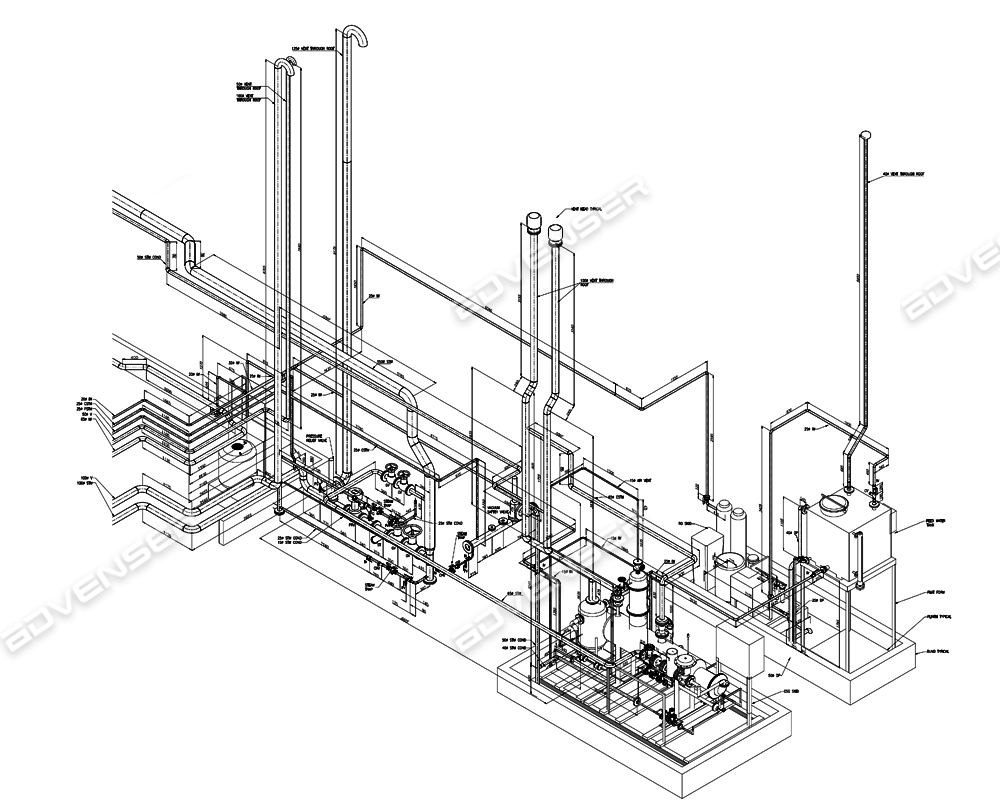
Isometric Piping Drawings Advenser
Instrumentation Today HOW TO READ AN ISOMETRIC PIPING DRAWING

How to read isometric drawing piping dadver

Piping Design Basics Piping Isometric Drawings Piping Isometrics
Piping Isometric Drawings Autodesk Community
Piping isometric drawing examples mazorama
How to read isometric piping drawings squaredbxe

How to read piping isometric drawing, Pipe fitter training, Watch the

How to read piping Isometric drawing YouTube
Automatic Piping Isometrics from 3D Piping Designs M4 ISO
Isometrics Are Usually Drawn From Information Found On A Plan And Elevation Views.
Web Isometrics Piping Fabrication And Erection Is Based On Piping Isometrics An Overview On Different Type Of Piping Drawing Used In Piping Project Construction By Vaibhav Raj After Designing A Complete 3D Model On Software Like Sp3D, Pdms, Autodesk, Etc It Is Important To Communicate The Same Information To The Fabrication And.
Web It Is The Most Important Deliverable Of Any Project Where Piping Plays A Vital Role.
Connection To Building Drain 708.1.3;
Related Post: