Drawing Views Standard
Drawing Views Standard - Most designers and engineers already know that. The height dimension is common to the front and side views. Ahead of the issb standards—ifrs s1 and ifrs s2—coming into effect in january 2024, the international sustainability standards board (issb) is providing new and updated resources to help companies apply the standards. The horizontal plane is rotated in the clockwise direction to draw the projection view of a 3d object on a 2d plane. We will implement this rule to draw engineering drawings in 1st angle and 3rd angle projection systems. All engineering directorate design organizations and their contractors shall adhere to the requirements of this manual when preparing gsfc engineering documentation for flight hardware and ground support systems. Web an engineering drawing is a subcategory of technical drawings. Web standard drawing views d c b a a b c d 8 7 6 5 4 3 2 1 8 7 6 5 4 3 2 1 dimensions are in inches tolerances: Web according to the rule of orthographic projection: Mach 1 bend 5 two place decimal.01 The width dimension is common to the front and top views. The purpose is to convey all the information necessary for manufacturing a product or a part. Web standard drawing views d c b a a b c d 8 7 6 5 4 3 2 1 8 7 6 5 4 3 2 1 dimensions are in inches tolerances:. Front, back, top, bottom, left side, right side, and isometric. Web standards see also v t e an engineering drawing is a type of technical drawing that is used to convey information about an object. There are three types of pictorial views: All engineering directorate design organizations and their contractors shall adhere to the requirements of this manual when preparing. The width dimension is common to the front and top views. Ahead of the issb standards—ifrs s1 and ifrs s2—coming into effect in january 2024, the international sustainability standards board (issb) is providing new and updated resources to help companies apply the standards. Standard drawing views' in the solidworks knowledge base. The horizontal plane is rotated in the clockwise direction. Front, back, top, bottom, left side, right side, and isometric. The depth dimension is common to the top and side views. A common use is to specify the geometry necessary for the construction of a component and is called a detail drawing. The width dimension is common to the front and top views. Web an engineering drawing is a subcategory. Web engineering drawing standards manual. Standard 3 view model view relative view predefined view empty view contents standard 3 view model view model view creates a single view based on a predefined view orientation. A simple way to visualize third. Web standard drawing views d c b a a b c d 8 7 6 5 4 3 2 1. Model break views within drawings. Most designers and engineers already know that. The actual view is a model view, usually in the isometric orientation. We will implement this rule to draw engineering drawings in 1st angle and 3rd angle projection systems. Web standard drawing views d c b a a b c d 8 7 6 5 4 3 2. View requirements are generally the same regardless of how they are created. Usually, a number of drawings are necessary to completely specify even a simple component. There are three types of pictorial views: Web approach to modeling user interface sketching concepts drawings and detailing drawings drawings overview creating drawings drafting multiple drawings detailing and drawings solidworks file utilities driveworksxpress floxpress. Web engineering drawing standards manual. The purpose is to convey all the information necessary for manufacturing a product or a part. Web n0031q $72 select important information regarding asme pdfs description this standard establishes the requirements for creating orthographic, and pictorial views on engineering drawing graphic sheets and in models. A drawing file contains one or more drawing sheets on. Standard drawing views' in the solidworks knowledge base. A simple way to visualize third. Most designers and engineers already know that. There are three types of pictorial views: The horizontal plane is rotated in the clockwise direction to draw the projection view of a 3d object on a 2d plane. Front, back, top, bottom, left side, right side, and isometric. How the views are laid out on a drawing depends on whether 3 rd angle or 1 st angle projection is being used. This makes understanding the drawings simple with little to no personal interpretation possibilities. Standard drawing views' in the solidworks knowledge base. Web when you create a drawing. Web exploded views in drawings. A drawing file contains one or more drawing sheets on which 2 dimensional and/or 3 dimensional scaled views of the solid models contained in part, assembly, or presentation files. There are three types of pictorial views: Web standard drawing views d c b a a b c d 8 7 6 5 4 3 2 1 8 7 6 5 4 3 2 1 dimensions are in inches tolerances: Web when you create a drawing from a part, curve, surface, or subassembly, you have the ability to create it without any views, by default, or with 4 standard views: 3.3 when sections or views are projected on the same or on other sheets, they Usually, a number of drawings are necessary to completely specify even a simple component. We will implement this rule to draw engineering drawings in 1st angle and 3rd angle projection systems. Web the seven standard views are: Web standards see also v t e an engineering drawing is a type of technical drawing that is used to convey information about an object. The horizontal plane is rotated in the clockwise direction to draw the projection view of a 3d object on a 2d plane. Web engineering graphics is used in the design process for visualization, communication, and documentation. Standard 3 view model view relative view predefined view empty view contents standard 3 view model view model view creates a single view based on a predefined view orientation. The two main types of views (or “projections”) used in drawings are: By gd&t basics on march 30, 2021. Standard drawing views' in the solidworks knowledge base.
Engineering Drawing Tutorials/Orthographic and sectional views ( T 11.3
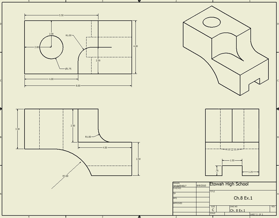
ENGRSEG4. Students will draw isometric and oblique drawings. Jake
Isometric Drawing Views
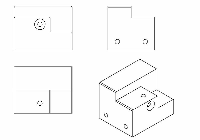
Engineering Drawing Views & Basics Explained Fractory
A Definitive Guide to Drawing Views
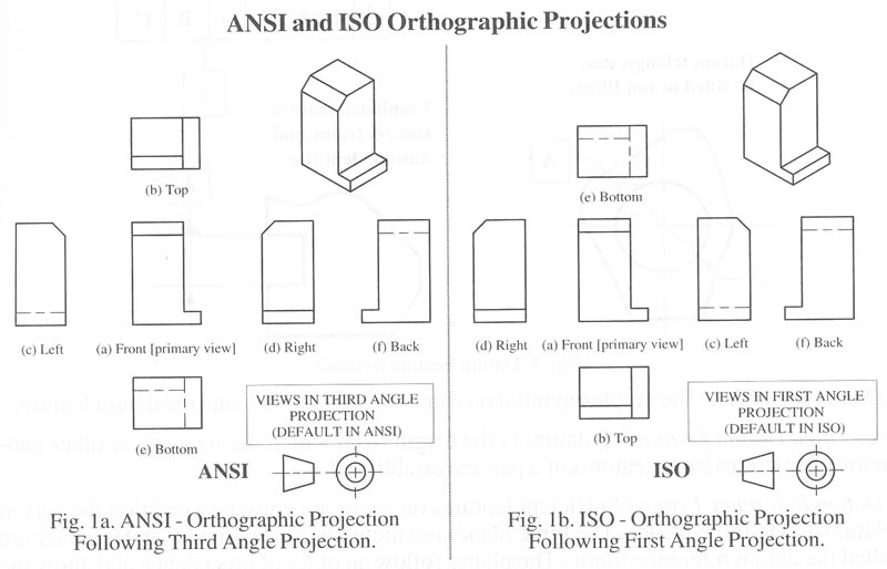
CME 475 Drawing Standards and Conventions
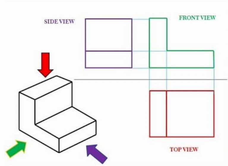
Engineering Drawing Views & Basics Explained Fractory

Basic Engineering Drawing Projection Knowledge Zone, The Online Support
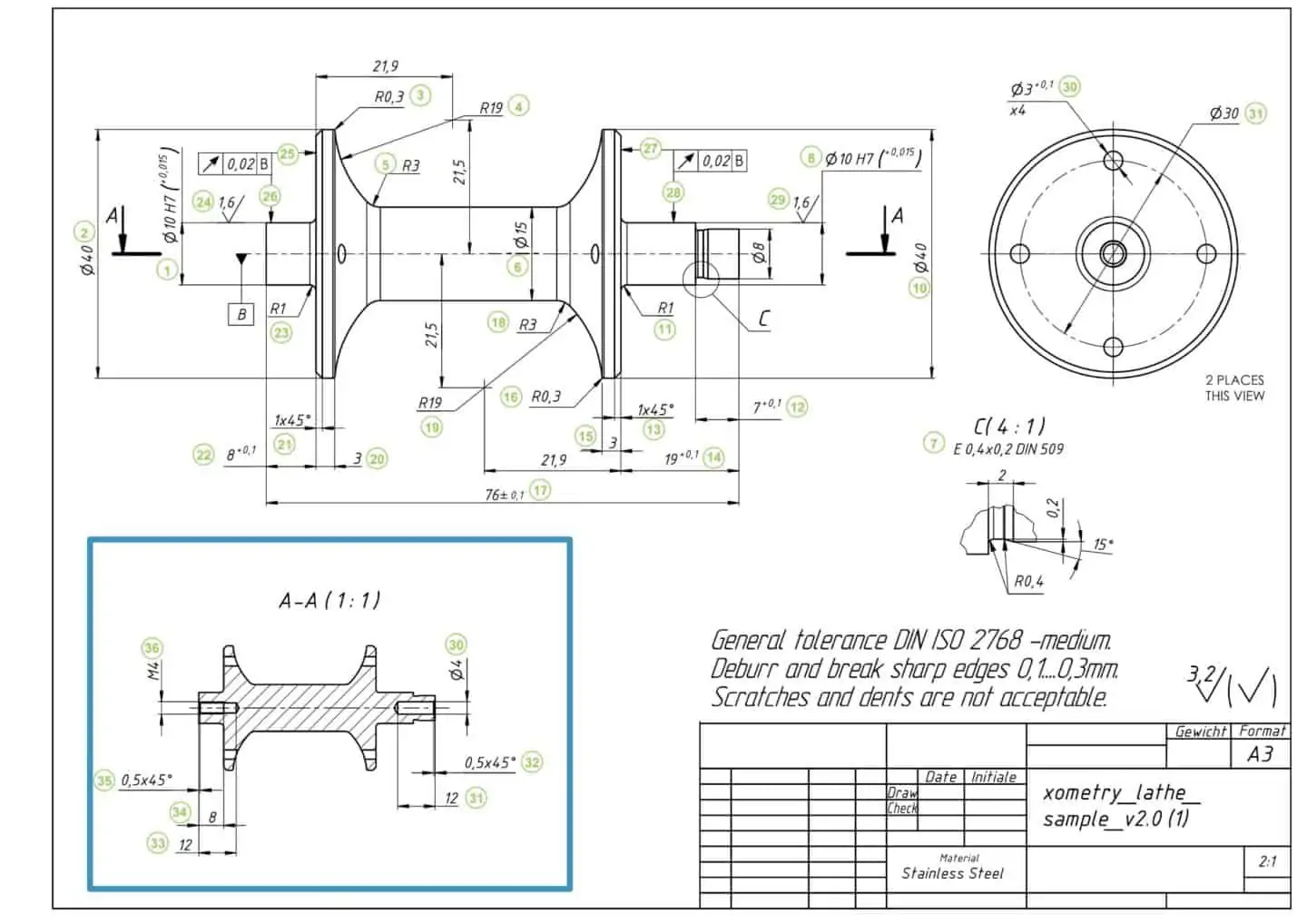
How To Prepare A Perfect Technical Drawing Xometry Europe
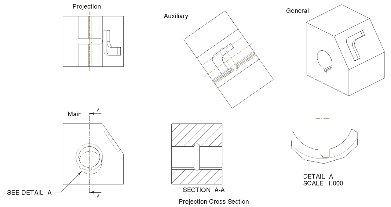
types of section views in engineering drawing howisphotographyartistic
How Drawing Projecton System Works.
A Common Use Is To Specify The Geometry Necessary For The Construction Of A Component And Is Called A Detail Drawing.
A Simple Way To Visualize Third.
For Simple Parts One Or Two View Drawings Will.
Related Post: