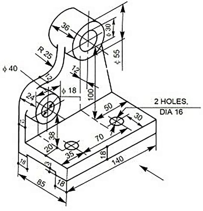
Elevation Isometric Drawing
Elevation Isometric Drawing - Web as an isometric for a particular line is developed, constant reference to the piping arrangement, section, or elevation drawings is essential. If the original drawings were drawn to isometric scales, then the distances can be read off directly from the original plan and elevation. Web an isometric drawing is a type of pictorial drawing in which three sides of an object can be seen in one view. The technique is intended to combine the illusion of depth, as in a perspective rendering, with the undistorted presentation of the object’s principal dimensions. Piping layouts will provide information on the pipe route, dimension, elevation, valve orientation, and coordinates. Web 19k views 1 year ago tutorials for pipe fitters and fabricators. Web identify views used in technical drawings including perspective, isometric, oblique, orthographic, plans, elevations, and sections. 10.2.2 constructing an isometric view from plan and elevation typically, the plan and elevation are drawn to the isometric scale and the distances The fitting, flange, and valve drawing symbols unique to isometrics are depicted. Isometrics in a single view provide a pictorial representation of the height, width and depth dimensions in a single view to provide a pictorial representation. By definition, isometrics drawings are a graphic representation of a 3d routed line in a 2d plane that combines height, length of pipe in a single drawing with a 30º angle on both sides from horizontal. Accurate drawing symbols, callouts, precise coordinates, and elevations provide intricate information to the fabricator. Web the process of drafting isometric drawings for a pipeline. Isometrics in a single view provide a pictorial representation of the height, width and depth dimensions in a single view to provide a pictorial representation. Web an explanation of how piping isometrics are created from plan and elevation views is explained. Web as an isometric for a particular line is developed, constant reference to the piping arrangement, section, or elevation. Web identify views used in technical drawings including perspective, isometric, oblique, orthographic, plans, elevations, and sections. It’s popular within the process piping industry because it can be laid out and drawn with ease and portrays the object in a. Also a nice extra extension puzzle at the end using 7 irregular solids to make a cube. 10.2.2 constructing an isometric. Web identify the pipe runs: Web it is the most important deliverable of any project where piping plays a vital role. Web isometrics are usually drawn from information found on a plan and elevation views. Quick!a simple tutorial to show how to draw simple 3d shapes as isometric drawings, and then give plan and elevation drawings for same 3d. It’s. Web in isometric drawings, the three principal axes make equal angles with the image plane. Piping layouts will provide information on the pipe route, dimension, elevation, valve orientation, and coordinates. The two main types of views (or “projections”) used in drawings are: Web a selection of 3 activities, in order of difficulty, for those 3d views topics. How to read. If the original drawings were drawn to isometric scales, then the distances can be read off directly from the original plan and elevation. Drawing symbols, callouts, coordinates, and elevations provide detailed information of the pipe's configuration and routing through the unit. The use of a north arrow in establishing pipe orientation and routing on the isometric is shown graphically. There. Drawing symbols, callouts, coordinates, and elevations provide detailed information of the pipe's configuration and routing through the unit. The two main types of views (or “projections”) used in drawings are: 3rd to 5th, 6th to 8th, high school use this interactive tool to create dynamic drawings on isometric dot paper. Web a selection of 3 activities, in order of difficulty,. The two main types of views (or “projections”) used in drawings are: To check details of lines connected to equipment nozzles, their elevations, etc. Web in isometric drawings, the three principal axes make equal angles with the image plane. 87k views 2 days ago. Web 19k views 1 year ago tutorials for pipe fitters and fabricators. Web we are concluding our first pipefitter series run with a video on how to draw isometric drawings. Also a nice extra extension puzzle at the end using 7 irregular solids to make a cube. Drawing symbols, callouts, coordinates, and elevations provide detailed information of the pipe's configuration and routing through the unit. Web a selection of 3 activities, in. 3rd to 5th, 6th to 8th, high school use this interactive tool to create dynamic drawings on isometric dot paper. Also a nice extra extension puzzle at the end using 7 irregular solids to make a cube. The two main types of views (or “projections”) used in drawings are: The fitting, flange, and valve drawing symbols unique to isometrics are. The use of a north arrow in establishing pipe orientation and routing on the isometric is shown graphically. Web in isometric drawings, the three principal axes make equal angles with the image plane. Use the piping plan and elevation views to identify these. Web it is the most important deliverable of any project where piping plays a vital role. Web piping layouts and sectional drawings: Web a selection of 3 activities, in order of difficulty, for those 3d views topics. Web isometrics are usually drawn from information found on a plan and elevation views. Accurate drawing symbols, callouts, precise coordinates, and elevations provide intricate information to the fabricator. Web types of views used in drawings. Web the process of drafting isometric drawings for a pipeline system involves referencing the arrangements of the pipelines, sections, and elevation drawings during its development. Piping layouts will provide information on the pipe route, dimension, elevation, valve orientation, and coordinates. There are three types of pictorial views: 3rd to 5th, 6th to 8th, high school use this interactive tool to create dynamic drawings on isometric dot paper. By definition, isometrics drawings are a graphic representation of a 3d routed line in a 2d plane that combines height, length of pipe in a single drawing with a 30º angle on both sides from horizontal. The symbols that represent fittings, valves and flanges are modified to adapt to the isometric grid. Draw figures using edges, faces, or cubes.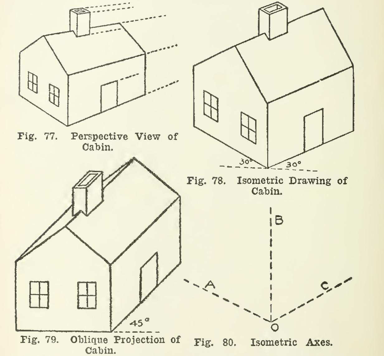
Isometric House Drawing at Explore collection of
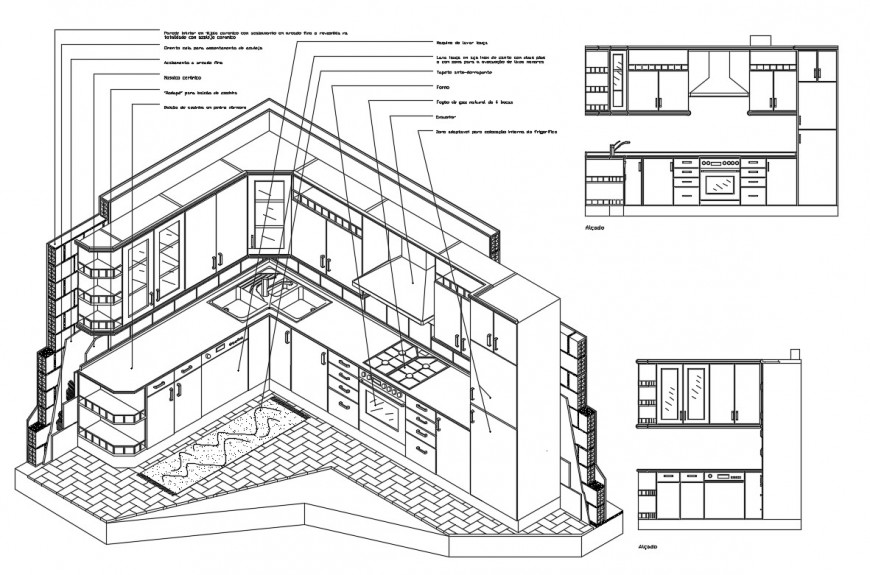
Kitchen isometric elevation, section and autocad drawing details dwg

Isometric View and Elevations. Staircase design, Steel stairs, Window
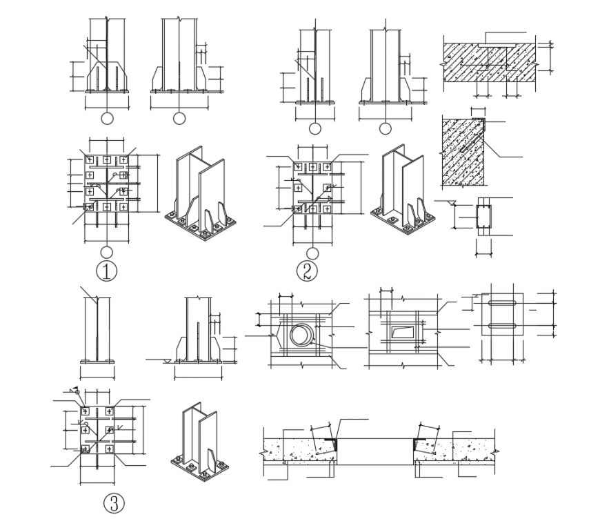
I beam isometric view with elevation and plan structure view dwg file
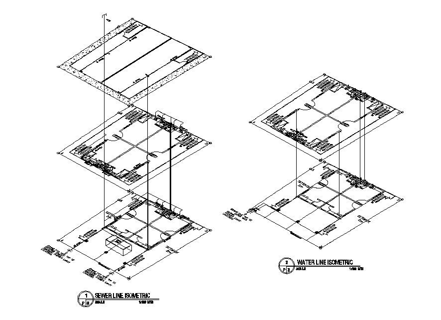
Sewer And Water Line Isometric Elevation Drawing DWG File Cadbull
Draw elevation, plan, side view from isometric using autocad by

Plans, Elevations and Isometric Drawings Teaching Resources

3D Isometric View Bungalow Elevation AutoCAD File Cadbull

3D Front Elevation, Side and Plan; Isometric Drawing Part 2 YouTube
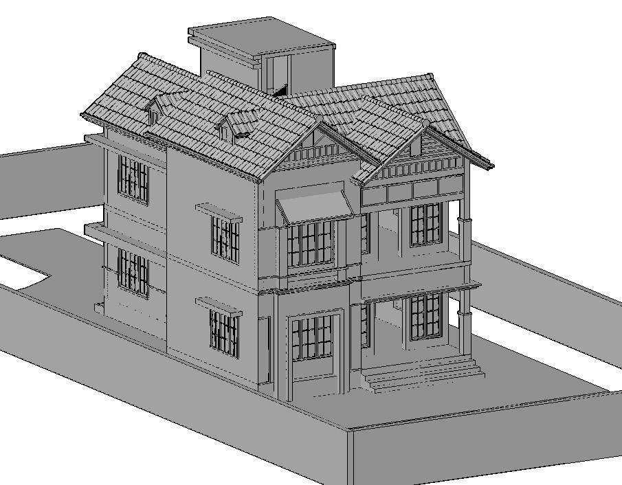
3D House Model Isometric Elevation Design DWG File Cadbull
Also A Nice Extra Extension Puzzle At The End Using 7 Irregular Solids To Make A Cube.
To Check Details Of Lines Connected To Equipment Nozzles, Their Elevations, Etc.
Web Isometric Drawing Tool Grade:
Web Selected Points On The Circle.
Related Post: