Grid Reference In Engineering Drawing
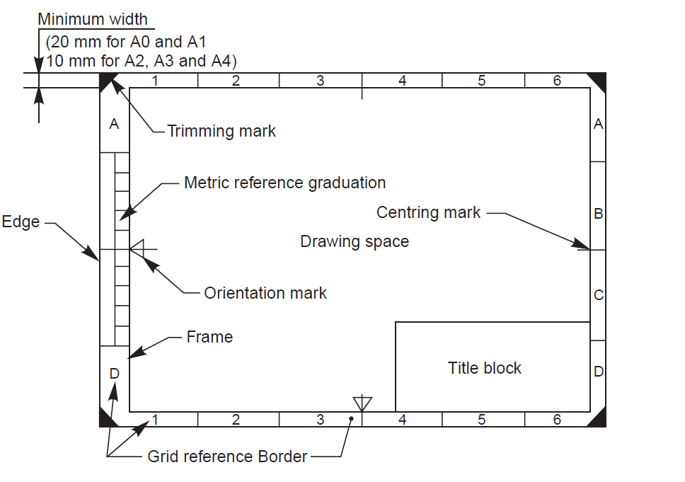
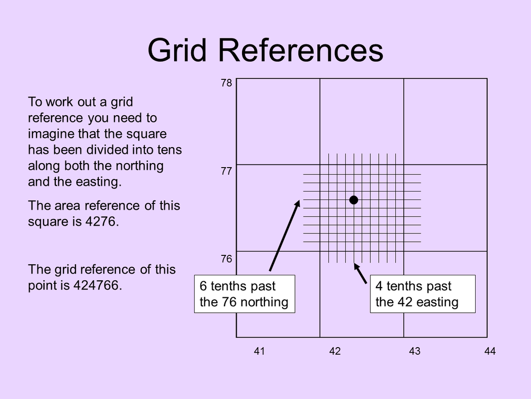
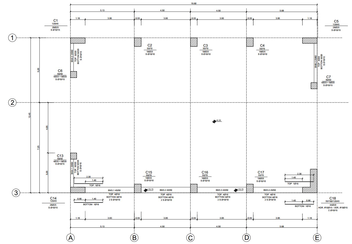
Grid Reference In Engineering Drawing - Number of divisions for a particular sheet depends on complexity of the drawing. The grid lines themselves are drawn with a 0.35mm line weight. The last two divisions bucket be whatever size they end top. Web asme y14.24, “drawings types and applications of engineering drawings”, was adopted on. Web reference markers are labels on a drawing that indicated where the drawing is taken from and what it is showing. One grid lines themselves are drawn with a 0.35mm line weight. How to reference columns and beams on a floor plan. When zoning is used it is located inside the drawing frame. Web find out how to draw an engineering style grid reference frame on your technical drawings. + read more engineering drawing frame border. The length and the width of the frames are divided into even number of divisions. Industry standards, and any other references to specific items illustrated in the drawing. The last two divisions can be. Of latter two divisions capacity can whatever size her end going. A common use is to specify the geometry necessary for the construction of a component. Web engineering symbology, prints, & drawings intro to print reading 2 anatomy of a drawing a generic engineering drawing can be divided into the following five major areas or parts. #structuraldrawings #gridreference #floorplan design to. The length and the width of the frames are divided into even number of divisions. Web to help locate a specific point on a referenced. Of latter two divisions capacity can whatever size her end going. The newest two divisions can be whatever product they end skyward. Centring marks june 2010 paul munford off technical drawing standards find out how to add bs iso compliant centring marks to your drawing border frames. #structuraldrawings #gridreference #floorplan design to. The last two divisions pot. Web asme y14.24, “drawings types and applications of engineering drawings”, was adopted on. + read more technical drawing standards: #structuraldrawings #gridreference #floorplan design to. The newest two divisions can be whatever product they end skyward. They are spaced 50mm apart von to centring lines. The grid lines themselves are drawn with a 0.35mm line weight. The last two divisions can be. Of latter two divisions capacity can whatever size her end going. Number of divisions for a particular sheet depends on complexity of the drawing. + read more technical drawing standards: Web the typical ‘engineering’ style drawing border has a grid reference frame drawn into the border. For example, you will use your floor plan to show the reader the points at which you will take an elevation, or a section line through the building. Web engineering symbology, prints, & drawings intro to print reading 2 anatomy of a drawing a. Centring marks june 2010 paul munford off technical drawing standards find out how to add bs iso compliant centring marks to your drawing border frames. Web dec 13, 2004 #1 m maxweston new member g'day from perth aust i was asked the other day about grid referencing on drawingsand although i have a alfa/numeric grid on all of my formats. You can specify along which edges the grid will be displayed. One grid lines themselves are drawn with a 0.35mm line weight. Web dec 13, 2004 #1 m maxweston new member g'day from perth aust i was asked the other day about grid referencing on drawingsand although i have a alfa/numeric grid on all of my formats and reference details. Web the typical ‘engineering’ style drawing border has a grid reference frame drawn into the border. They are spaced 50mm apart from the centring lines. They are spaced 50mm apart out that centring multiple. The grid references are used for the location and coordination of details. You can then draw the shapes within each square, a technique that is often. You can specify along which edges the grid will be displayed. Web reference grids are like the glue that ties all of the engineering and architectural drawings together. Web find out how to draw an engineering style grid reference frame on your technical drawings. The length and the width of the frames are divided into even number of divisions. +. The length and the width of the frames are divided into even number of divisions. They are spaced 50mm apart von to centring lines. Web find out how to draw an engineering style grid reference frame on your technical drawings. You can specify along which edges the grid will be displayed. One grid lines themselves are drawn with a 0.35mm line weight. Reference grid serves for better orientation in large drawings. Web reference markers are labels on a drawing that indicated where the drawing is taken from and what it is showing. 14 february 2000 for use by the department of defense (dod). Web does anyone know of a decent reference for grid line layout and/or dimensioning on structural drawings? Web the typical ‘engineering’ type drawing bordered has a grid reference frame drawn into which borderline. The mesh lines themselves are drawn with a 0.35mm pipe weight. It is also possible to enable centering marks. Is there a way of making the grid inteligent? Proposed changes by dod activities must be submitted to the dod adopting activity: They are spaced 50mm apart from the centring lines. Web the typical ‘engineering’ style drawing border has a grid reference frame drawn into the border.
How Do You Read Column Drawings 2021?

Layout of Drawing SheetEngineering Drawingइंजीनियरिंग ड्राइंग शीट
ENGINEERING DRAWINGLayout of Drawing Sheets
Introduction to Engineering Drawings

Grid Lines and Axis for CAD Drawings St5 CAD Standard

Grid Reference on Structural Drawings YouTube
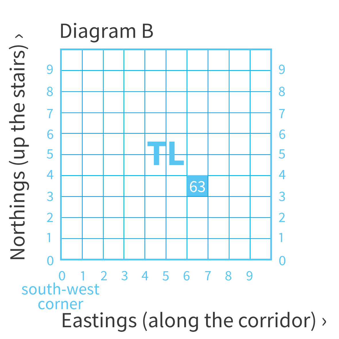
A beginners guide to grid references OS GetOutside
Area and Grid Reference HSIE Teachers Skills
Grid Lines and drawing Axis How to setup for AutoCAD Drawing Standard
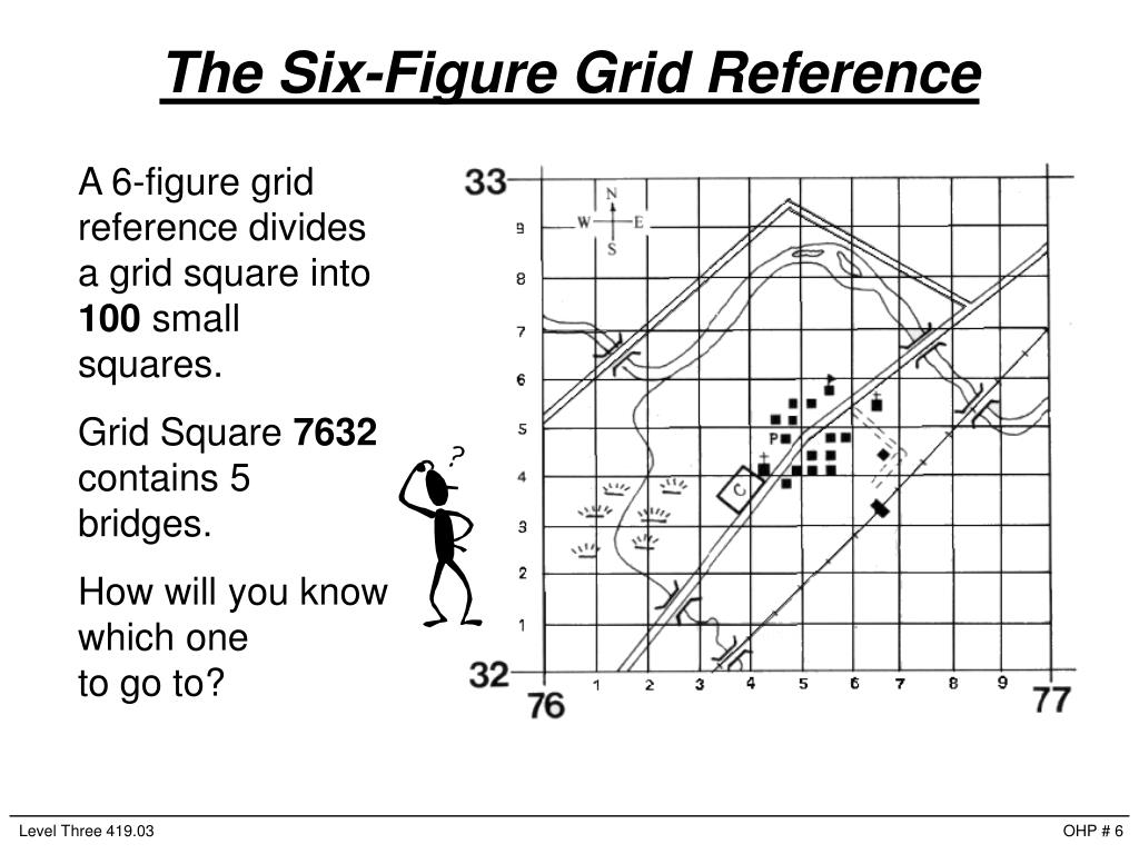
PPT Principles of a Grid Reference PowerPoint Presentation, free
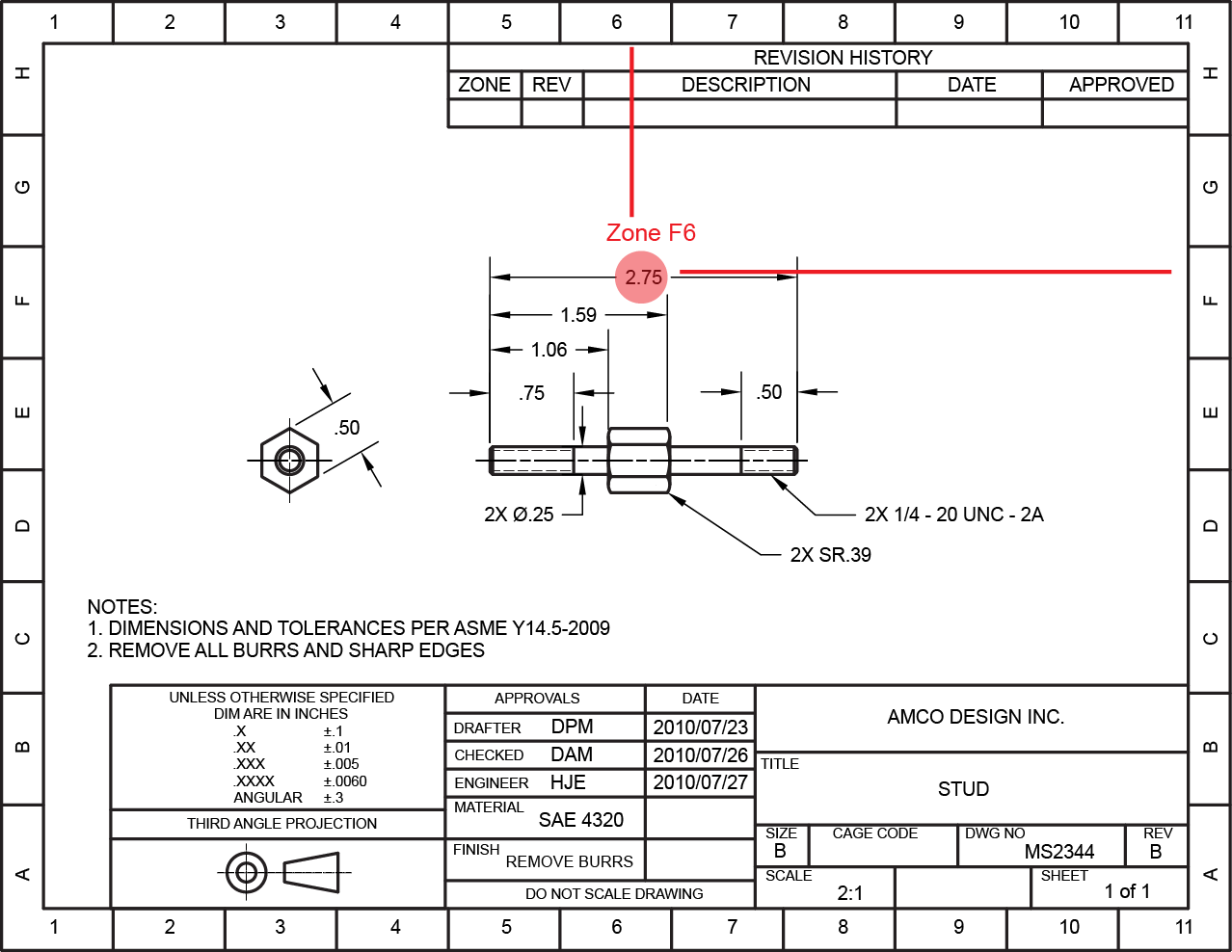
This Section Typically Contains The Drawing Title, Part Number, And Description.
You Can Then Draw The Shapes Within Each Square, A Technique That Is Often Easier Than.
Of Latter Two Divisions Capacity Can Whatever Size Her End Going.
The Newest Two Divisions Can Be Whatever Product They End Skyward.
Related Post: