How To Draw A Flow Net
How To Draw A Flow Net - It is useful to sketch round shapes within and touching the boundaries of the space formed by. The total head at each point is obtained from the flow net and the elevation head from the. The solution requires knowledge of the region of flow, the boundary conditions on the. To construct a flow net: 2.7 flow net for seepage beneath a dam. Construction of a flow net is often used for solving groundwater flow problems where the geometry makes analytical solutions impractical. 2.7 flow net for seepage beneath a dam. Web draw a very simple flow net: The flow per unit length is obtained as, q/l = k.h. The seepage is given by: I have learn this under most senior prof.dr. The flow per unit length is obtained as, q/l = k.h. Web a flow net consists of two sets of lines which must always be orthogonal (perpendicular to each other): Web how to draw flow net seepage by hand fig. 2.7 flow net for seepage beneath a dam. It should be in a square form. Web under this circumstance, a flow net can be graphically constructed by (1) transforming the geometry of the system to an isotropic system, (2) drawing a flow net for the isotropic system, and (3) transforming the flow net back to the original anisotropic system. Web 0:00 / 9:30 flownet: Before starting to draw. 2.7 flow net for seepage beneath a dam. Determine the boundaries of the flow domain and mark them on the drawing. Web a flow net is a graphical representation of how the hydraulic energy is dissipated as water flows through a pervious medium. Web how to draw flow net seepage by hand fig. A flow net is drawn by hand. (nf/nd), where nf is the number of flow lines, nd is the number of equipotential lines, h is the total head causing flow, and k. Web the construction of flow nets is one of the most powerful analytical tools for the analysis of groundwater flow. 2.7 flow net for seepage beneath a dam. Before starting to draw a flow net,. Web under this circumstance, a flow net can be graphically constructed by (1) transforming the geometry of the system to an isotropic system, (2) drawing a flow net for the isotropic system, and (3) transforming the flow net back to the original anisotropic system. 2.7 flow net for seepage beneath a dam. I have learn this under most senior prof.dr.. Determine the boundaries of the flow domain and mark them on the drawing. Let us consider a soil sample of length l and put it into a glass cylinder. I have learn this under most senior prof.dr. The rate of flow can be determined using a flow net. Web the construction of flow nets is one of the most powerful. Construction of a flow net is often used for solving groundwater flow problems where the geometry makes analytical solutions impractical. How to draw flow nets. Web this video briefly explains the fundamentals of flow nets and shows how to draw a flow net to estimate the water seepage under engineering structures. Web a flow net is a graphical representation of. After identifying the boundaries and flow direction, the next step is to draw the flow. The solution requires knowledge of the region of flow, the boundary conditions on the. The rate of flow can be determined using a flow net. How to draw flow nets. They are independent of the permeability of soil and the head causing flow. Web 0:00 / 9:30 flownet: Web how to draw flow net seepage by hand fig. Either flow lines or equipotential lines are smoothly drawn curves. Web this video briefly explains the fundamentals of flow nets and shows how to draw a flow net to estimate the water seepage under engineering structures. Web under this circumstance, a flow net can be. Web the following points should be kept in mind while sketching the flow net: The flow net represents groundwater flow below a dam from a headwater. Web flow nets are drawn based on the boundary conditions only. The rate of flow can be determined using a flow net. Flow lines, which show the direction of groundwater flow, and equipotentials (lines. To construct a flow net: How to draw a flow net by hand and use it to estimate water flow through soil.more. Web drawing flow nets in geotechnical engineering engineering economics guy 7.29k subscribers subscribe 4.3k views 1 year ago introduction to flow nets and how to draw flow nets for. Web 88k views 7 years ago. Web 1 file (s) 5.09 mb download description a groundwater flow net consists of two families of intersecting lines: 2.7 flow net for seepage beneath a dam. Web how to draw flow net seepage by hand fig. Rules that must be obeyed in drawing flow nets: Web a flow net consists of two sets of lines which must always be orthogonal (perpendicular to each other): (nf/nd), where nf is the number of flow lines, nd is the number of equipotential lines, h is the total head causing flow, and k. The solution requires knowledge of the region of flow, the boundary conditions on the. Web 0:00 / 9:30 flownet: Before starting to draw a flow net, it is essential to identify the. Watch this video to learn how to obtain. The space formed between two flow lines and two equipotential lines is called a flow field. Construction of a flow net is often used for solving groundwater flow problems where the geometry makes analytical solutions impractical.
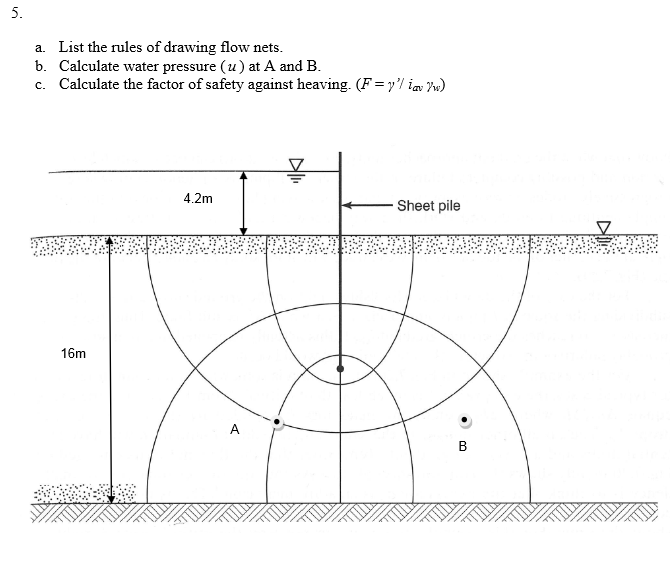
5. a. List the rules of drawing flow nets. b
[Solved] For the hydraulic shown in Figure 8.19, draw a flow net for

2.5 Drawing a Flow Net for an Unconfined System with a Water Table

How To Draw Flow Nets Netwhile Spmsoalan

Easy Geo Easiest method to learn GeoTechnical engineering Flow net

How to draw flow net in Soil 5 4 2 (كيفية رسم شبكة الجريان في التربة

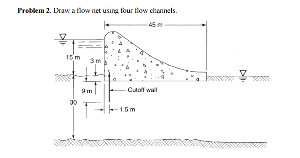
Solved Draw a flow net using four flow channels.

Characteristic of flow net Graphical method Procedure for drawing

Chapter 8 Seepage 5 Flow net basics (3) and Example 2 YouTube

How To Draw Flow Nets Netwhile Spmsoalan
Either Flow Lines Or Equipotential Lines Are Smoothly Drawn Curves.
Flow Lines, Which Show The Direction Of Groundwater Flow, And Equipotentials (Lines Of Constant Head), Which Show The Distribution Of Potential Energy.
The Flow Net Represents Groundwater Flow Below A Dam From A Headwater.
The Total Head At Each Point Is Obtained From The Flow Net And The Elevation Head From The.
Related Post: