How To Draw Shear And Moment Diagram
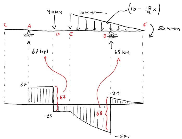
How To Draw Shear And Moment Diagram - Q 5 (a) draw the shear force and the bending moment diagram for the frame shown in figure sa with the distributed load of \ ( 10 \mathrm {kn} / \mathrm {m} \) on the vertical member and the point load of \ ( 20 \mathrm {kn} \) on the horizontal member. Web this video explains how to draw shear force diagram and bending moment diagram with easy steps for a simply supported beam loaded with a concentrated load. When drawing the shear diagram, we are going to get a steeply rising parabola that flattens out to horizontal at x =7. In general the process goes like this:1) calcul. Web the first step in calculating these quantities and their spatial variation consists of constructing shear and bending moment diagrams, \(v(x)\) and \(m(x)\), which are the internal shearing forces and bending moments induced in. Web lined up below the shear diagram, draw a set of axes. You will understand the relationship between external loading and the shear forces and bending moments they induce. Being able to draw shear force diagrams (sfd) and bending moment diagrams (bmd) is a critical skill for any student studying statics, mechanics of materials, or structural engineering. Web shear and moment diagrams are graphs which show the internal shear and bending moment plotted along the length of the beam. Web once you have the reactions, draw your free body diagram and shear force diagram underneath the beam. Web the graph of the above equation is as shown below. And the area and location of centroid are defined as follows. Web lined up below the shear diagram, draw a set of axes. A = area of moment diagram. Degree = degree power of the moment diagram. Neglect the mass of the beam in each problem. I explain the calculus involved in drawing them and the steps are written out below.check out. Finally calculating the moments can be done in the following steps: Plot shear force and bending moment. This page will walk you through what shear forces and bending moments are, why they are useful, the. Skyciv beam tool guides users along a professional beam calculation workflow, culminating in the ability to view and determine if they comply with your region's design codes. Being able to draw shear force diagrams (sfd) and bending moment diagrams (bmd) is a critical skill for any student studying statics, mechanics of materials, or structural engineering. In general the process goes. M x = moment about a section of distance x. Write shear and moment equations for the beams in the following problems. Web lined up below the shear diagram, draw a set of axes. When drawing the shear diagram, we are going to get a steeply rising parabola that flattens out to horizontal at x =7. To calculate the bending. The #1 source for free engineering tutorials. To calculate the bending moment of a beam, we must work in the same way we did for the shear force. Web the first step in calculating these quantities and their spatial variation consists of constructing shear and bending moment diagrams, \(v(x)\) and \(m(x)\), which are the internal shearing forces and bending moments. Q 5 (a) draw the shear force and the bending moment diagram for the frame shown in figure sa with the distributed load of \ ( 10 \mathrm {kn} / \mathrm {m} \) on the vertical member and the point load of \ ( 20 \mathrm {kn} \) on the horizontal member. Web you will be fully competent in drawing. This video show how to analyze a parabolic load on a beam, solve for reactions, and. In general the process goes like this:1) calcul. To calculate the bending moment of a beam, we must work in the same way we did for the shear force. Web shear and moment diagrams are graphs which show the internal shear and bending moment. Degree = degree power of the moment diagram. Web this video explains how to draw shear force diagram and bending moment diagram with easy steps for a simply supported beam loaded with a concentrated load. Lined up below the shear diagram, draw a set of axes. Web lined up below the shear diagram, draw a set of axes. The #1. Web mechanical engineering questions and answers. Web this video explains how to draw shear force diagram and bending moment diagram with easy steps for a simply supported beam loaded with a concentrated load. Web shear force and bending moment diagrams are powerful graphical methods that are used to analyze a beam under loading. A = area of moment diagram. Lined. In general the process goes like this:1) calcul. Write shear and moment equations for the beams in the following problems. Plot shear force and bending moment. Web the first step in calculating these quantities and their spatial variation consists of constructing shear and bending moment diagrams, \(v(x)\) and \(m(x)\), which are the internal shearing forces and bending moments induced in.. Degree = degree power of the moment diagram. If you’re not in the mood. Neglect the mass of the beam in each problem. Being able to draw shear force diagrams (sfd) and bending moment diagrams (bmd) is a critical skill for any student studying statics, mechanics of materials, or structural engineering. When drawing the shear diagram, we are going to get a steeply rising parabola that flattens out to horizontal at x =7. In general the process goes like this:1) calcul. Web main steps to construct shear force and bending moment diagrams draw a free body diagram of the beam with global coordinates (x) calculate the reaction forces using equilibrium equations ( ∑ forces = 0 and ∑ moments = 0 ). Web solve for all external forces and moments, create a free body diagram, and create the shear diagram. I explain the calculus involved in drawing them and the steps are written out below.check out. The #1 source for free engineering tutorials. You will understand the relationship between external loading and the shear forces and bending moments they induce. From left to right, make “cuts” before and after each reaction/load. Web 0:00 / 14:58 how to draw a shear and moment diagram (easy) aka engineer 4.1k subscribers subscribe 1.3k share save 313k views 11 years ago for the first part on drawing the moment. Skyciv beam tool guides users along a professional beam calculation workflow, culminating in the ability to view and determine if they comply with your region's design codes. Web you will be fully competent in drawing shear force and bending moment diagrams for statically determinate beams and frames. Web 𝐌𝐲 𝐄𝐧𝐠𝐢𝐧𝐞𝐞𝐫𝐢𝐧𝐠 𝐍𝐨𝐭𝐞𝐛𝐨𝐨𝐤 for notes!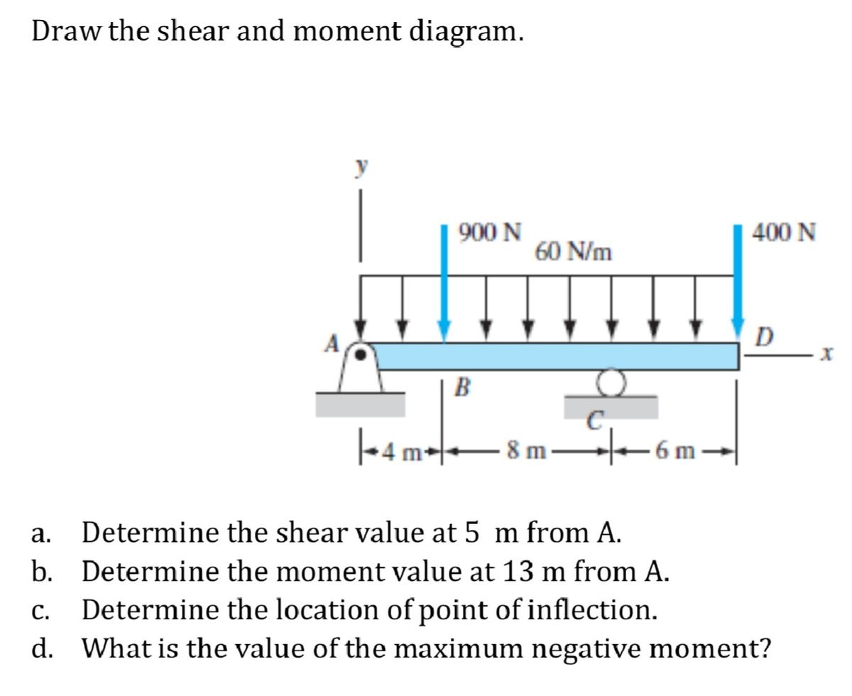
Answered Draw the shear and moment diagram. 900… bartleby
The Ultimate Guide to Shear and Moment Diagrams

Learn How To Draw Shear Force And Bending Moment Diagrams Engineering

Learn How To Draw Shear Force And Bending Moment Diagrams Engineering

Learn How To Draw Shear Force And Bending Moment Diagrams Engineering

How to draw shear and moment diagrams YouTube

Ultimate Guide to Shear Force and Bending Moment Diagrams

Solved Draw The Shearforce And Bendingmoment Diagrams F...

Shear and moment diagrams indimg

Drawing Shear and Moment Diagrams for Beam YouTube
A = 1 N + 1Bh A = 1 N + 1 B H.
Web Shear And Bending Moment Diagrams Are Analytical Tools Used In Conjunction With Structural Analysis To Help Perform Structural Design By Determining The Value Of Shear Force And Bending Moment At A Given Point.
Barred X = Location Of Centoid.
M X = Moment About A Section Of Distance X.
Related Post: