Iso Drawings Piping
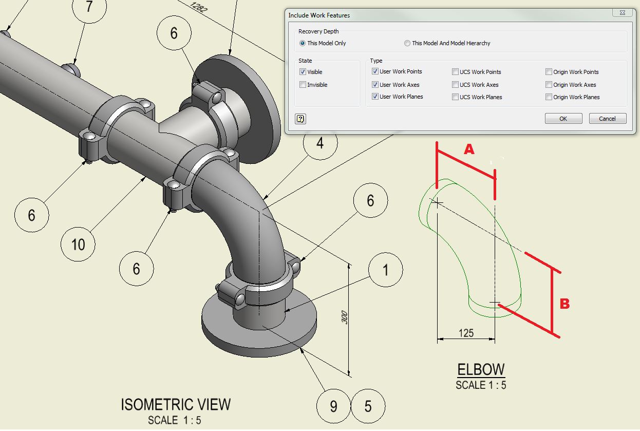
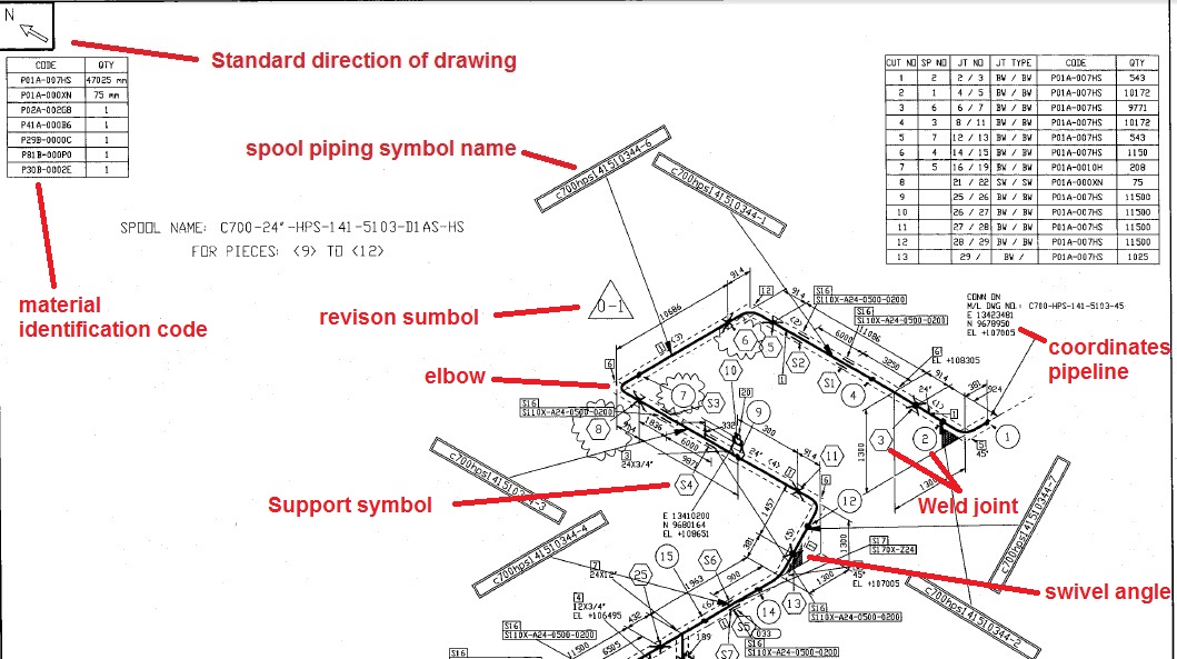
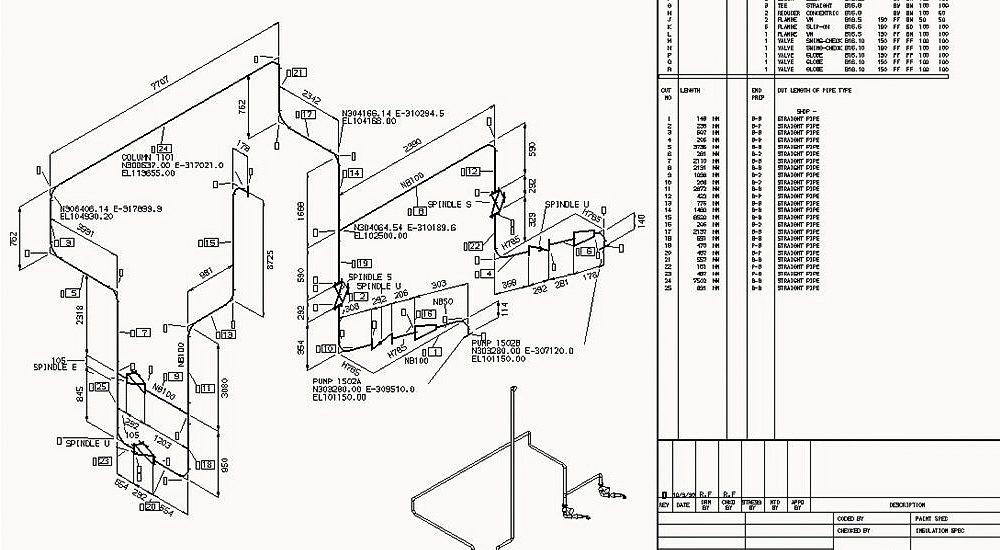
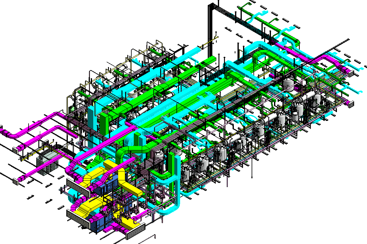
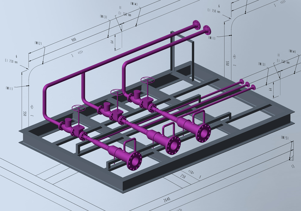
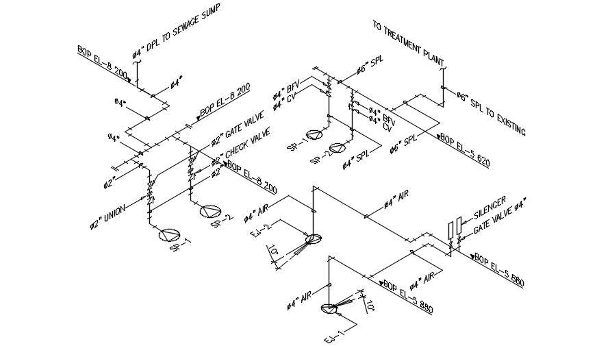
Iso Drawings Piping - These systems follow local regulations, including plumbing codes, and may need to adhere to standards such as awwa c900 (polyvinyl chloride (pvc) pressure pipe and fabricated. Bottom section of isometric drawing contains:. Web what is an isometric drawing? In this article, a few of the salient points are discussed. Web an isometric drawing is nothing but a detailed orthographic drawing that represents the details of 3d structure of the piping system in a 2d format. They accurately and clearly document the pipework design and contain all the information necessary for fabrication. Web about this page piping isometrics roy a. Main graphic section consist of isometric representation of a pipe line route in 3d space, which includes following information : Isometric drawings are typically used to show the details of a piping system, such as the size and type of piping, the direction of flow of the fluids, and the location of valves, pumps, and other equipment nozzles. Web piping isometric drawing consists of three sections. Web codes and standards: Web piping isometric drawing consists of three sections. Web the inception of isometric drawings, also known as piping isometrics, marks a crucial milestone in the world of engineering. These systems follow local regulations, including plumbing codes, and may need to adhere to standards such as awwa c900 (polyvinyl chloride (pvc) pressure pipe and fabricated. So engineers. So engineers and designers must be aware of the isometric preparation steps. First create a drawing sheet in din a4 or a3 and activate the isometric grid. Section of left or right of piping isometric drawing includes:. Isometric drawings are, by definition, a visual depiction of a 3d routed line in a 2d plane that combines pipe height and length. It’s popular within the process piping industry because it can be laid out and drawn with ease and portrays the object in a. Calculations for piping data from isometric drawing. Web we are concluding our first pipefitter series run with a video on how to draw isometric drawings. In this article, a few of the salient points are discussed. Bottom. Web here is an overview of the steps we need to take when creating iso pipe drawings: Common tools include straight pipe elbows and. Web easy isometric is the first pipe isometric drawing app that helps users make detailed isometric drawings in the field and without the need for tedious reference materials. Web pipeline isometric drawings: Draw the route of. A piping isometric drawing is a 2d drawing in which piping is represented like a 3d drawing. Web what is piping isometric drawings? Web the inception of isometric drawings, also known as piping isometrics, marks a crucial milestone in the world of engineering. Isometrics are usually drawn from information found on a plan and elevation views. Isometric drawings are, by. Web piping isometric drawing consists of three sections. Second, draw the pipeline with the help of simple lines. These drawings have become an indispensable tool for representing complex pipeline structures. Main graphic section consist of isometric representation of a pipe line route in 3d space, which includes following information : Unlike orthographics, piping isometrics allow the pipe to be drawn. Web how to read piping isometric drawing symbols. They accurately and clearly document the pipework design and contain all the information necessary for fabrication. Isometric drawings are typically used to show the details of a piping system, such as the size and type of piping, the direction of flow of the fluids, and the location of valves, pumps, and other. These systems follow local regulations, including plumbing codes, and may need to adhere to standards such as awwa c900 (polyvinyl chloride (pvc) pressure pipe and fabricated. All directions of the pipe may. Web pipeline isometric drawings: In this article, a few of the salient points are discussed. Second, draw the pipeline with the help of simple lines. Calculations for piping data from isometric drawing. Web easy isometric is the first pipe isometric drawing app that helps users make detailed isometric drawings in the field and without the need for tedious reference materials. The main body of an isometric piping drawing consists of the. With the help of sophisticated computer aided design (cad) tools, piping engineers and designers. Web reading a piping isometric drawing basic training. Web piping isometric drawing is one of the most important deliverables of the piping discipline as it provides complete information of the piping routeto be erected at the construction site. The main body of a piping isometric drawing is consist of:. These systems follow local regulations, including plumbing codes, and may need. Isometric lines can be in vertical direction and two other directions at 30° from horizontal. Web what is piping isometric drawing? Section of left or right of piping isometric drawing includes:. These drawings have become an indispensable tool for representing complex pipeline structures. Web it is the most significant output of any project where plumbing is essential. So engineers and designers must be aware of the isometric preparation steps. An explanation of how piping isometrics are created from plan and elevation views is explained. A piping isometric drawing is a 2d drawing in which piping is represented like a 3d drawing. Π x diameter of the. When using software, it is. How to read iso drawings. In this article, a few of the salient points are discussed. Web the inception of isometric drawings, also known as piping isometrics, marks a crucial milestone in the world of engineering. With the help of sophisticated computer aided design (cad) tools, piping engineers and designers can produce isometric drawings from 3d models with ease. Web pipeline isometric drawings: Create a drawing sheet for isometrics.
Piping Isometric Drawing at Explore collection of

Piping Design Basics Piping Isometric Drawings Piping Isometrics
Piping Isometric Drawings Autodesk Community
Learn isometric drawings (piping isometric)
PIPING ISO
Automatic Piping Isometrics from 3D Piping Designs M4 ISO
Piping Isometric Drawing at Explore collection of
Automatic Piping Isometrics from 3D Piping Designs M4 ISO

Isometric Piping Drawings Advenser
Piping isometric drawing examples planninglio
Common Tools Include Straight Pipe Elbows And.
Web Here Is An Overview Of The Steps We Need To Take When Creating Iso Pipe Drawings:
Second, Draw The Pipeline With The Help Of Simple Lines.
Isometric Drawings Are, By Definition, A Visual Depiction Of A 3D Routed Line In A 2D Plane That Combines Pipe Height And Length In A Single Drawing With A 30° Angle On Either Side Of The Horizontal.
Related Post: