Isometric Pipe Drawing
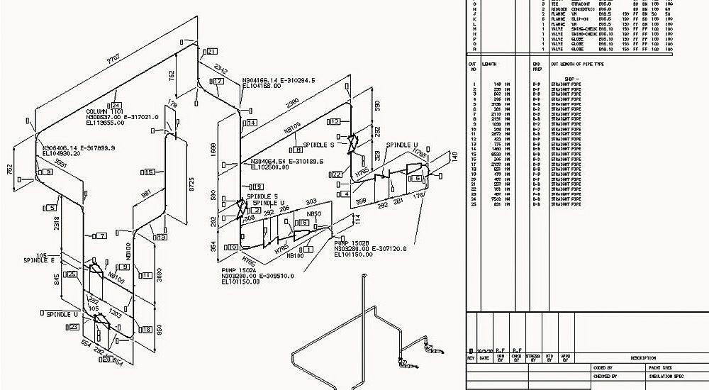
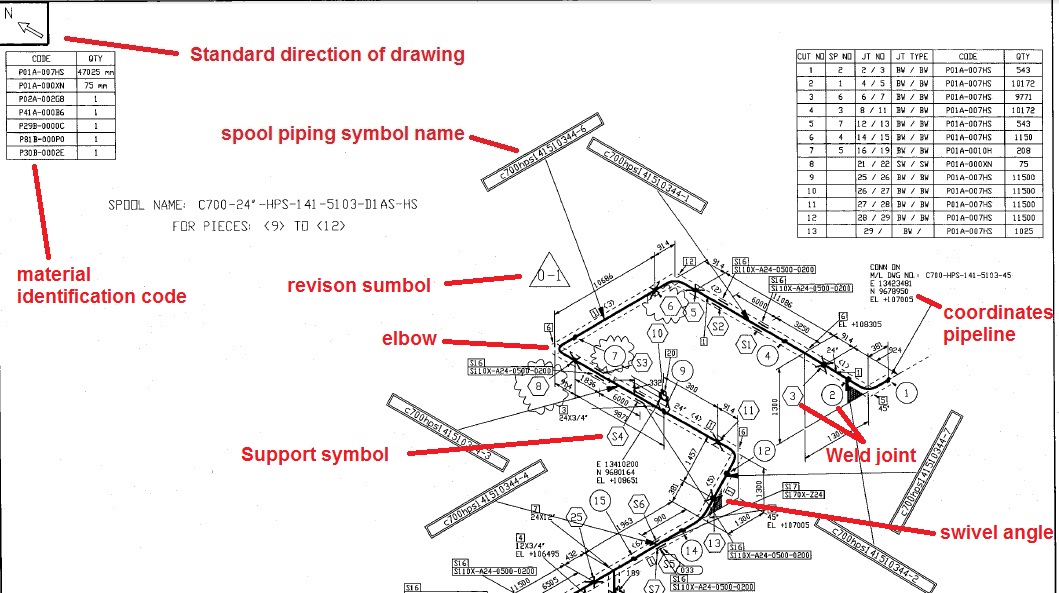
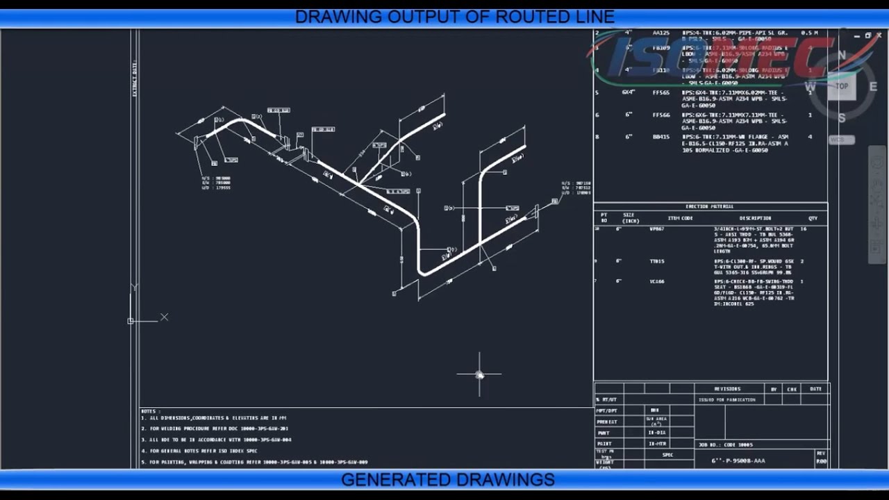
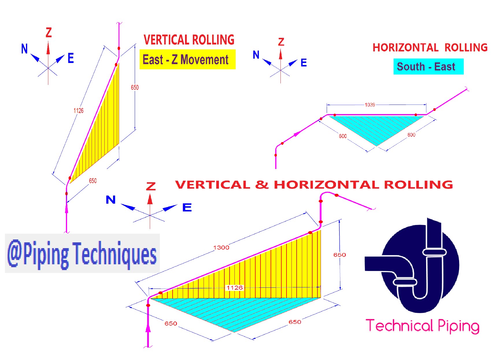
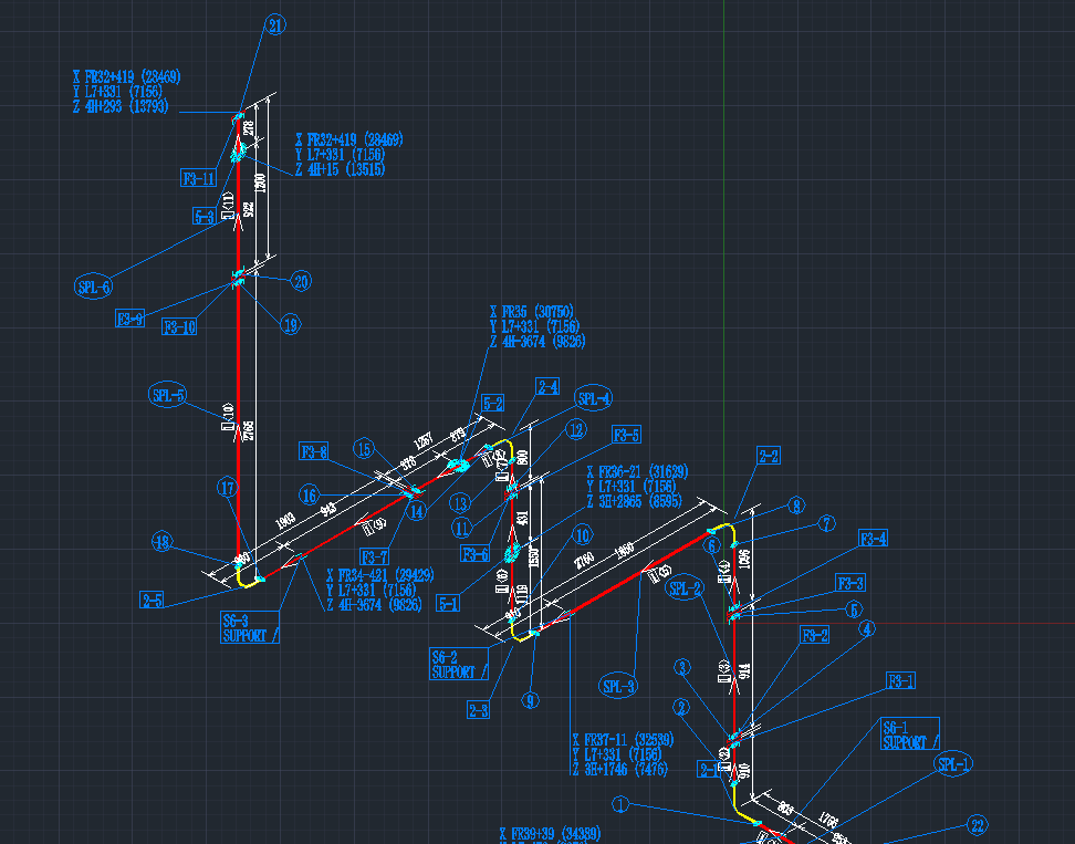
Isometric Pipe Drawing - Isometrics are usually drawn from information found on a plan and elevation views. In this article, a few of the salient points are discussed. Web an isometric drawing is a type of pictorial drawing in which three sides of an object can be seen in one view. The drawing axes of the isometrics intersect at an angle of 60°. Web draw piping isometrics efficiently. In isometric drawings, pipes are represented as lines. Isometric drawings are typically used to show the details of a piping system, such as the size and type of piping, the direction of flow of the fluids, and the location of valves, pumps, and other equipment nozzles. Lighter lines show connected pipe, and are not parts of the symbols. Flow direction is a critical aspect of piping systems. Web how to read isometric drawing in a piping isometrics drawing, pipe is drawn according to it’s length, width an.more.more how to read, study piping isometric drawing how to. Web understanding flow direction. Web isometric drawings are, by definition, a visual depiction of a 3d routed line in a 2d plane that combines pipe height and length in a single drawing with a 30° angle on either side of the horizontal. In isometric drawings, pipes are represented as lines. Main graphic section consist of isometric representation of a pipe. Web put information in your drawings and diagrams into perspective with an isometric drawing. Are tagged with the same codes used on the p&id and ga. Pipes are shown as single lines, and symbols are used to represent pipe fittings, valves, pipe gradients, and welds. Web an isometric drawing is a type of pictorial drawing in which three sides of. Web iso pipes are typically drawn using specialized software such as avicad which supports isometric drawings. Line number flow direction piping components Web understanding flow direction. Web isometric piping drawings are not scale drawings, so they are dimensioned. Web we are concluding our first pipefitter series run with a video on how to draw isometric drawings. Create isometric drawings in minutes: The symbols that represent fittings, valves and flanges are modified to adapt to the isometric grid. Automated bill of materials no more tedious material tracking when creating a pipe isometric drawing. When it comes to pipes, isometric drawing plays a crucial role in conveying complex designs to engineers, fabricators, and construction teams. Web isometric piping. Web put information in your drawings and diagrams into perspective with an isometric drawing. In isometric drawings, pipes are represented as lines. In this article, a few of the salient points are discussed. The symbols that represent fittings, valves and flanges are modified to adapt to the isometric grid. Pipes are shown as single lines, and symbols are used to. It’s popular within the process piping industry because it can be laid out and drawn with ease and portrays the object in a. Isometrics are usually drawn from information found on a plan and elevation views. How to read iso drawings. Isometric drawings are typically used to show the details of a piping system, such as the size and type. Lighter lines show connected pipe, and are not parts of the symbols. When it comes to pipes, isometric drawing plays a crucial role in conveying complex designs to engineers, fabricators, and construction teams. Are tagged with the same codes used on the p&id and ga. Reading a piping isometric drawing basic training. 3 clicks to draw a pipe, 3 clicks. So engineers and designers must be aware of the isometric preparation steps. Lighter lines show connected pipe, and are not parts of the symbols. Isometric drawings are typically used to show the details of a piping system, such as the size and type of piping, the direction of flow of the fluids, and the location of valves, pumps, and other. Web the process of drafting isometric drawings for a pipeline system involves referencing the arrangements of the pipelines, sections, and elevation drawings during its development. Weld joint type and its location; Line number flow direction piping components Web piping isometric drawing software is an essential tool for piping engineers and designers to create detailed isometric drawings of piping systems. Import. Web the main body of a piping isometric drawing is consist of: So engineers and designers must be aware of the isometric preparation steps. Web understanding flow direction. Web a piping isometric drawing is a technical drawing that depicts a pipe spool or a complete pipeline using an isometric representation. Web isometric piping drawings are not scale drawings, so they. 3 clicks to draw a pipe, 3 clicks to add an elbow, 1 click to add a dimension and 3 clicks to print. Import idf or pcf files. Automated bill of materials no more tedious material tracking when creating a pipe isometric drawing. Web isometric piping drawings are not scale drawings, so they are dimensioned. Pipes are shown as single lines, and symbols are used to represent pipe fittings, valves, pipe gradients, and welds. Create isometric drawings in minutes: Accurate drawing symbols, callouts, precise coordinates, and elevations provide intricate information to the fabricator. Web how to read isometric drawing in a piping isometrics drawing, pipe is drawn according to it’s length, width an.more.more how to read, study piping isometric drawing how to. Web piping isometric drawing is one of the most important deliverables of the piping discipline as it provides complete information of the piping routeto be erected at the construction site. Web isometric drawings are, by definition, a visual depiction of a 3d routed line in a 2d plane that combines pipe height and length in a single drawing with a 30° angle on either side of the horizontal. This section delves into how to interpret and deduce flow direction from isometric drawings: Web draw piping isometrics efficiently. Web a piping isometric drawing is a technical drawing that depicts a pipe spool or a complete pipeline using an isometric representation. Web the process of drafting isometric drawings for a pipeline system involves referencing the arrangements of the pipelines, sections, and elevation drawings during its development. Web understanding flow direction. Main graphic section consist of isometric representation of a pipe line route in 3d space, which includes following information :
How to Draw Isometric Pipe Drawings in Autocad Gautier Camonect

Piping Isometric Drawing at Explore collection of
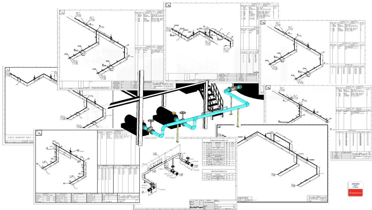
Automatic Piping Isometrics from 3D Piping Designs M4 ISO
Learn isometric drawings (piping isometric)
Piping Isometric Drawings Autodesk Community
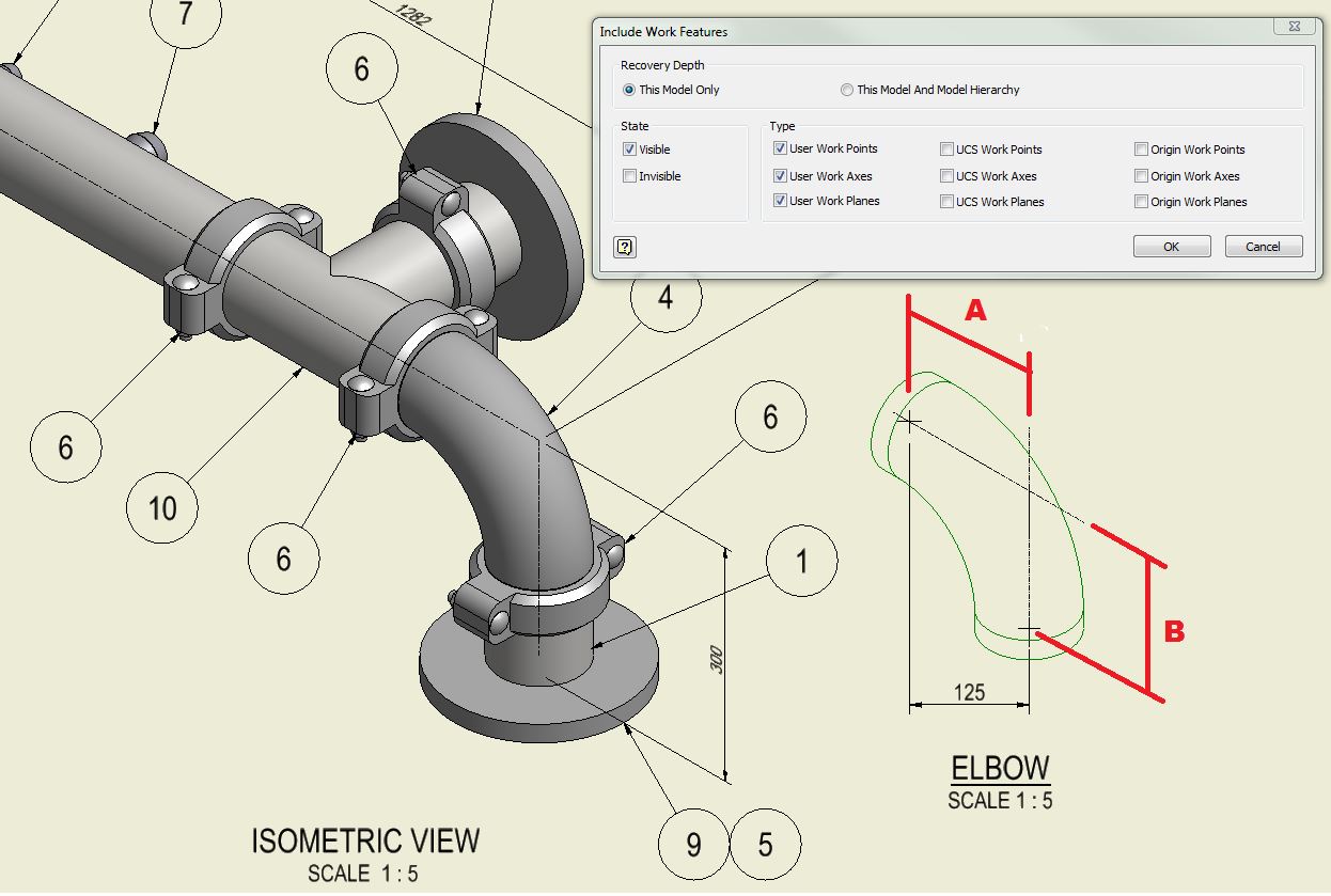
How to create piping isometric drawings with SOLIDWORKS
Piping Isometric Drawing at Explore collection of
Isometric Pipe Drawing at GetDrawings Free download
Piping isometric drawing examples mazorama

Isometric Piping Drawings Advenser
The Main Body Of An Isometric Piping Drawing Consists Of The Following:
Web We Are Concluding Our First Pipefitter Series Run With A Video On How To Draw Isometric Drawings.
How To Read Iso Drawings.
Symbols Are Shown In Black Lines.
Related Post: