One Line Electrical Drawings
One Line Electrical Drawings - Newer versions office 2010 office 2007 on the file tab, click new, and then search for engineering templates. So easy, in fact, practically anyone can use it. When interpreting a single line diagram, you should always start at the top where the highest voltage is and work your way down to the lowest voltage. Web use the electrical engineering drawing type in visio professional or visio plan 2 to create electrical and electronic schematic diagrams. Lets go through a industrial single line diagram. Electrical elements such as circuit breakers, transformers, capacitors, bus bars, and conductors are shown by standardized. Click one of the following: This chart shows the most frequently used symbols. It will have one single line shown for bus (or cable) to represent all three phases. Also, look at electrical power distribution diagrams, including protective relays, and other one lines. Web use the electrical engineering drawing type in visio professional or visio plan 2 to create electrical and electronic schematic diagrams. Newer versions office 2010 office 2007 on the file tab, click new, and then search for engineering templates. So easy, in fact, practically anyone can use it. The software has a positioning grid (that can be disabled), the components. Newer versions office 2010 office 2007 on the file tab, click new, and then search for engineering templates. Basics 8 aov elementary & block diagram : As the name suggests, a single line is used to denote the multiple power lines such as in 3 phase system. Web serving as a map of the electrical distribution system in a facility,. These components come from the generic base provided with the software but can also be customized according to the project. Web electrical one line diagram design. Also, look at electrical power distribution diagrams, including protective relays, and other one lines. Remember that you are using a single line to represent multiple conductors. Web online circuit diagram maker draw circuits, wiring. This chart shows the most frequently used symbols. Basics 8 aov elementary & block diagram : Web electrical one line diagram design. Basics 9 4.16 kv pump schematic : Basic electrical circuits and logic fluid power industrial control systems These components come from the generic base provided with the software but can also be customized according to the project. Basics 10 480 v pump schematic : Web in the field of electrical diagrams, they are equivalent to contents or abstract in the field of written articles. Web online circuit diagram maker draw circuits, wiring diagrams, and more in minutes. These components come from the generic base provided with the software but can also be customized according to the project. This condenses the space and complexity of the diagram for simpler troubleshooting. Web serving as a map of the electrical distribution system in a facility, an sld documents conductors, transformers, overcurrent protective devices (ocpds) and other electrical devices and safety. Diagrams start at the top of the page with the incoming source of a system’s power. One of the key tools in developing and documenting an electrical power system is the single line diagram (shortened sld). First of all, power system designers should always communicate their design requirements through a combination of drawings, schedules and technical specifications. Basics 9 4.16. Basics 8 aov elementary & block diagram : It is a simplified drawing of the whole system or a portion of the power system that shows the electrical placement of all major equipment. It will have one single line shown for bus (or cable) to represent all three phases. Web serving as a map of the electrical distribution system in. These components come from the generic base provided with the software but can also be customized according to the project. Newer versions office 2010 office 2007 on the file tab, click new, and then search for engineering templates. Basics 9 4.16 kv pump schematic : As the name suggests, a single line is used to denote the multiple power lines. Basics 8 aov elementary & block diagram : Try before you buy download a free demo copy today. Basics 10 480 v pump schematic : So easy, in fact, practically anyone can use it. It’s the smartest, easiest way to decide! Basics 8 aov elementary & block diagram : Try before you buy download a free demo copy today. Electrical elements such as circuit breakers, transformers, capacitors, bus bars, and conductors are shown by standardized. Basic electrical circuits and logic fluid power industrial control systems Basics 9 4.16 kv pump schematic : They are called “single line” because only one line is used to represent all three phases, and only one pole symbols are used to represent multipole switchgear or metering transformers placed in all lines. So easy, in fact, practically anyone can use it. It will have one single line shown for bus (or cable) to represent all three phases. This condenses the space and complexity of the diagram for simpler troubleshooting. One of the key tools in developing and documenting an electrical power system is the single line diagram (shortened sld). The software has a positioning grid (that can be disabled), the components have. Web in the field of electrical diagrams, they are equivalent to contents or abstract in the field of written articles. This chart shows the most frequently used symbols. Electrical power grids primarily consist of. Web we usually depict the electrical distribution system by a graphic representation called a single. Newer versions office 2010 office 2007 on the file tab, click new, and then search for engineering templates.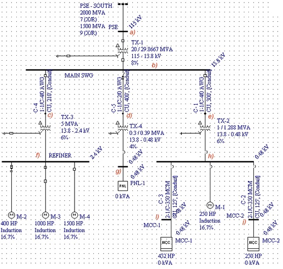
Electrical Single Line Diagram Part Two Electrical Knowhow
Intelligent One Line Diagram Electrical SingleLine Diagram ETAP
Electrical Single Line Diagram Part Two Electrical Knowhow
How To Calculate and Draw a Single Line Diagram For The Power System EEP
Electrical SingleLine Diagram Electrical OneLine Diagram ETAP
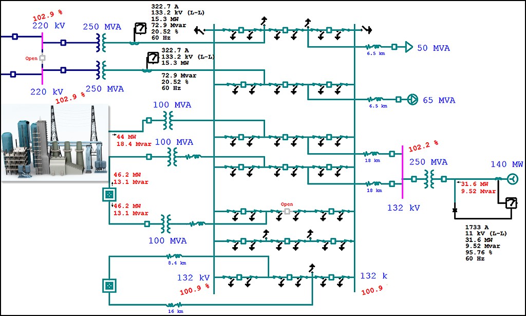
Electrical SingleLine Diagram Electrical OneLine Diagram ETAP
single line diagram of electrical house wiring Wiring Diagram and

Electrical Single Line Diagram Part Two Electrical Knowhow
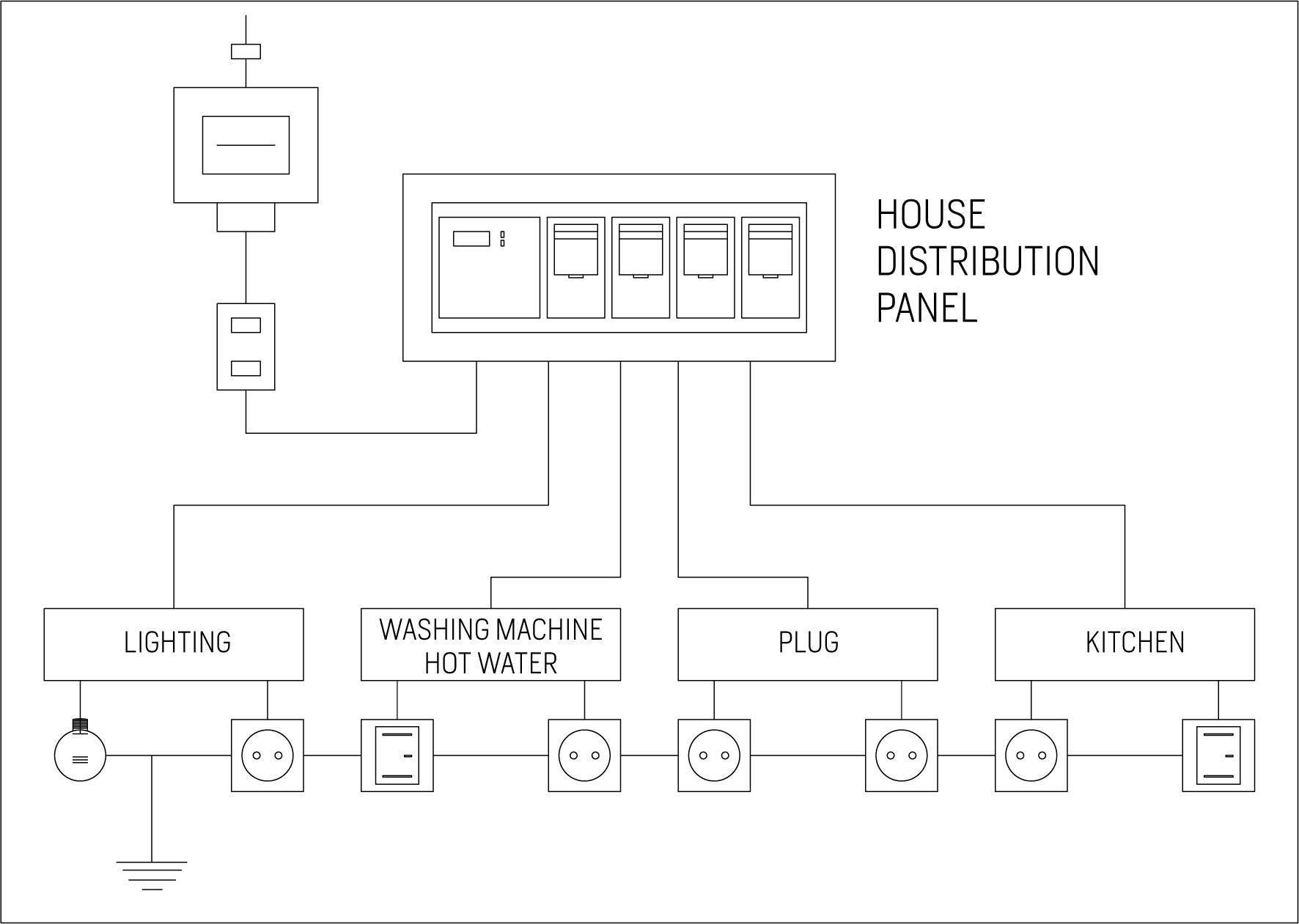
Single Line Diagram Of Electrical House Wiring Wiring Diagram and

Electrical one line diagram pnasit
Click One Of The Following:
It’s The Smartest, Easiest Way To Decide!
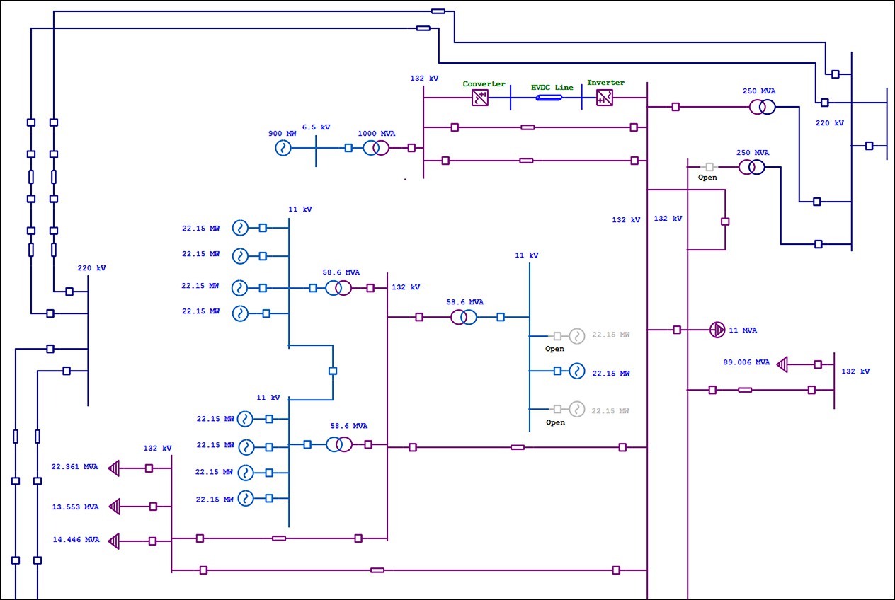
When Interpreting A Single Line Diagram, You Should Always Start At The Top Where The Highest Voltage Is And Work Your Way Down To The Lowest Voltage.
Web Serving As A Map Of The Electrical Distribution System In A Facility, An Sld Documents Conductors, Transformers, Overcurrent Protective Devices (Ocpds) And Other Electrical Devices And Safety Mechanisms To Aid In Many Areas Of Design And Maintenance While Reducing Confusion.
Related Post: