Pipe Isometric Drawing
Pipe Isometric Drawing - Web this topic of discussion gives basic information for piping isometrics, its preparation details, drafting requirements, material take off in isometrics, supports etc. Web 42k views 1 year ago tutorials for pipe fitters and fabricators. Piping isometrics drawing are a type of pictorial drawings that show the three principal dimensions of an object in one view. Pipes are shown as single lines, and symbols are used to represent pipe fittings, valves, pipe gradients, and welds. Lighter lines show connected pipe, and are not parts of the symbols. Web isometric drawings are, by definition, a visual depiction of a 3d routed line in a 2d plane that combines pipe height and length in a single drawing with a 30° angle on either side of the horizontal. Web pipeline isometrics are detailed drawings used in engineering and design to represent the 3d layout of a pipeline system on a 2d surface. Pipes are drawn with a single line irrespective of the line sizes, as well as the other configurations such as reducers,. Π x diameter of the. Symbols like fittings, valves and flanges are modified to adapt to the isometric grid. 3 clicks to draw a pipe, 3 clicks to add an elbow, 1 click to add a dimension and 3 clicks to print. Calculations for piping data from isometric drawing. Web piping isometric drawing consists of three sections. As you can see, this drawing is very simple and quick to implement. When using software, it is. So engineers and designers must be aware of the isometric preparation steps. One vertical & two at 30° from horizontal isometric lines can be. Are tagged with the same codes used on the p&id and ga. Import idf or pcf files. Π x diameter of the. First create a drawing sheet in din a4 or a3 and activate the isometric grid. Lighter lines show connected pipe, and are not parts of the symbols. Isometric drawings are commonly used in industries such as the oil and gas industry, petrochemical industry, and plumbing for planning, design, construction, and pipeline maintenance. Web isometric drawings are, by definition, a visual. Bottom section of isometric drawing contains:. Isometric drawings are commonly used in industries such as the oil and gas industry, petrochemical industry, and plumbing for planning, design, construction, and pipeline maintenance. Pipes are shown as single lines, and symbols are used to represent pipe fittings, valves, pipe gradients, and welds. Are tagged with the same codes used on the p&id. As you can see, this drawing is very simple and quick to implement. Web the isometric view shows the same pipe as in the orthographic view. Web features of piping isometric drawing it is not drawn to the scale, but it is proportionate with the exact dimensions represented. Web iso pipes are typically drawn using specialized software such as avicad. Pipes are shown in the same size. Second, draw the pipeline with the help of simple lines. Automated bill of materials no more tedious material tracking when creating a pipe isometric drawing. Web pipeline isometrics are detailed drawings used in engineering and design to represent the 3d layout of a pipeline system on a 2d surface. Pipes are shown as. The main body of an isometric piping drawing consists of the following: Π x diameter of the. When using software, it is. First create a drawing sheet in din a4 or a3 and activate the isometric grid. In this article, a few of the salient points are discussed. Web this topic of discussion gives basic information for piping isometrics, its preparation details, drafting requirements, material take off in isometrics, supports etc. Line number flow direction piping components Web piping isometric drawing is one of the most important deliverables of the piping discipline as it provides complete information of the piping routeto be erected at the construction site. Web. When using software, it is. Web features of piping isometric drawing it is not drawn to the scale, but it is proportionate with the exact dimensions represented. 3 clicks to draw a pipe, 3 clicks to add an elbow, 1 click to add a dimension and 3 clicks to print. Automated bill of materials no more tedious material tracking when. First create a drawing sheet in din a4 or a3 and activate the isometric grid. Import idf or pcf files. Reading a piping isometric drawing basic training. The red lines show the pipe, the black dots are the butt welds and a, b and c are the dimensions of front to. Web piping isometric drawings are essential documents in the. Web draw piping isometrics efficiently. Web features of piping isometric drawing it is not drawn to the scale, but it is proportionate with the exact dimensions represented. The red lines show the pipe, the black dots are the butt welds and a, b and c are the dimensions of front to. Pipes are drawn with a single line irrespective of the line sizes, as well as the other configurations such as reducers,. The main body of a piping isometric drawing is consist of:. Web piping isometric drawings are essential documents in the field of mechanical engineering, particularly in industries such as petrochemicals, oil and gas, and power generation. Reading a piping isometric drawing basic training. Isometric drawings are typically used to show the details of a piping system, such as the size and type of piping, the direction of flow of the fluids, and the location of valves, pumps, and other equipment nozzles. Web isometric piping drawings are not scale drawings, so they are dimensioned. Create a drawing sheet for isometrics. Web create the piping isometric drawing manually 1. Create isometric drawings in minutes: 3 clicks to draw a pipe, 3 clicks to add an elbow, 1 click to add a dimension and 3 clicks to print. Line number flow direction piping components Pipes are shown as single lines, and symbols are used to represent pipe fittings, valves, pipe gradients, and welds. Web the isometrics drawing are created from information found on a plan and elevation views.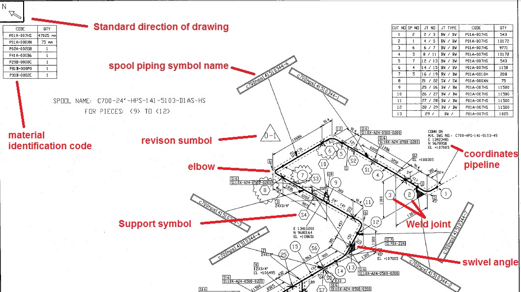
Learn isometric drawings (piping isometric)

Piping Isometric Drawing at Explore collection of

Isometric Piping Drawings Advenser

How to read isometric drawing piping dadver

How to read piping isometric drawing, Pipe fitter training, Watch the

How to read piping Isometric drawing YouTube

Piping Design Basics Piping Isometric Drawings Piping Isometrics
Isometric Pipe Drawing at GetDrawings Free download
Instrumentation Today HOW TO READ AN ISOMETRIC PIPING DRAWING
Automatic Piping Isometrics from 3D Piping Designs M4 ISO
They Serve As Precise Illustrations Providing Essential Information About The Layout, Dimensions, Materials, And Key Components Of A Pipeline System.
Isometric Drawings Are Commonly Used In Industries Such As The Oil And Gas Industry, Petrochemical Industry, And Plumbing For Planning, Design, Construction, And Pipeline Maintenance.
Web The Isometric View Shows The Same Pipe As In The Orthographic View.
Symbols Are Shown In Black Lines.
Related Post: